Table of Contents
- 7.1. Monitor Functions – Options for Monitoring
- 7.2. Mixing Functions – Configuring Internal Buses
- 7.3. Input Pools – Properties
- 7.4. Synchronisation
- 7.5. Potentiometers
- 7.6. Mute Logics
- 7.7. Selector Source Lists
- 7.8. Group Logic - Join Channels in Groups
- 7.9. Inserts - Patching External Audio Devices into Fader Channels
- 7.10. Global Pool Lines - Using Pool Signals between several Devices
- 7.11. Fader Channels – Configuring Signal Sources for Faders
- 7.12. Channel Assignment – Assigning Fader Channels and DSP Processing
- 7.13. Output Functions
- 7.14. Super Output Functions
- 7.15. Fixed Processing – Defining Fixed DSP Functions
- 7.16. Output Routing
In the node Audio System of the project tree, you can configure the audio functions of the RM4200D. First, select the node of the desired Device. Now several tabs and further sub-branches are available in the project tree to set up the various options. The options are described in this chapter, you find the general description of the functions in the volume System Reference of this manual.
In this tab you define how the monitor system of the RM4200D is performing.
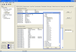
Here you can configure for the individual monitor buses which audio signal should be used as default source. This source is put on the appropriate bus after switching on the RM4200D or after a reset. It is also active when no monitor key is activated. (If you press an active key again, the assigned source is deactivated and the monitor bus receives the preset signal again.)
For each Monitor Bus 1...6 you can select the desired signal in the column Source separately. You can use any signal available on the TDM bus. The preset value is Program Bus 1; to mute the bus, you have to select None as audio source.
In order to assign an audio source, first click on the row with the desired monitor bus. (You can also double click the row to open the Audio Sources Window.)
In the Audio Sources Window select the desired audio source. Then click the button Assign, to assign the source. Alternatively, you can also select the desired source by double clicking or by Drag&Drop.
If there is a Global Pool Line reserved for a monitor bus, there is a label Global Pool in the column Info. (see also Global Pool Lines - Using Pool Signals between several Devices)
The button Clear All sets all Default Monitor Bus Sources to None (Mute).
![[Note]](../pics/note.gif) | Note |
|---|---|
If you define a preset source for a monitor bus, but do not assign a key to this source, the signal is switched on “in the background”, no key is shining. To avoid any misunderstanding for the user, you should configure no monitor key just for Audio Source = None! | |
Here you can assign a Source List to each Rotary Monitor Selector used in the configuration. Up to 10 different lists with a total of 150 entries are available. You can assign the selectable sources of the signal lists under Audio System/Selector Source Lists. (see also Selector Source Lists)
You can distribute the 10 signal lists arbitrarily to the Rotary Monitor Selectors and the Output Selectors of the Clean Feed System. (See also next section, Mixing Functions).
To assign the signal list, first mark the desired Rotary Monitor Selector and then select the desired list from the drop down menu Select Source List.
If there is a Global Pool Line reserved for a Rotary Monitor Selector, there is a label Global Pool in the column Info. (see also Global Pool Lines - Using Pool Signals between several Devices)
