| Select default display
text | | RM4200D | Display of the
firmware version available in the Device, e.g. “RM4200D V5.01.54” Default setting, recommended for at least one Module
per system. Overwritten at activation of the ACCESS function
in the Fader Channel, if Fader Module and Control Module belongs
to the same Access Group.
(see also Configuring Module Options)
|
| Device Name | Display of the
Device name, max. 16 digits. Overwritten at activation of the ACCESS function
in the Fader Channel, if Fader Module and Control Module belong
to the same Access Group.
|
| Timer 1…12 (this menu entry is available
for the timers 1 to 12) | Display of a
timer; max. 12 timers per system possible. With this function, you can also implement “Slave” displays
for timers. The timer display is overwritten at activation of the ACCESS function
in the Fader Channel, if Fader Module and Control Module belong
to the same Access Group.
|
| Default Rotary Monitor Selector | | Selector Number 1…10 | Similar to the
key function Rotary Monitor Select, but the
configured Rotary Monitor Selector is constantly
displayed.
(see function Rotary Monitor Select) With this, you can extend the monitor key sets generated
with Monitor Bus 1...6 or use the selector
independently for monitoring or routing. You have to assign a Source List with
audio sources to any Rotary Monitor Selector under Audio
System/Monitor Functions/Rotary Monitor Selector.
(see Rotary Monitor
Selector) Define the selectable sources of the Source
Lists under Audio System/Selector
Source Lists. You can use up to 10 different Source
Lists.
(see Output Selector Source List) You can use Rotary Monitor Selectors as
audio sources for Output Functions only.
You find them in the window Audio Sources Window under Monitor
Functions/Rot. Monitor Selector 1...10L,R. Rotary Monitor Selectors can
not be used as sources for other DSP functions, e.g. Fixed Processing or
for Output Routing. (For this, you have to
use an Output Function!) Monitor buses themselves are no audio
channels on the TDM bus system, but are created internally using
special routing functions!
|
| Selector Number 1…6 | The Rotary
Monitor Selectors 1…6 are available as source
for the Monitor buses 1...6 and can be assigned
to the corresponding Monitor Bus as source of a monitor key in the Audio
Sources Window under Monitor Functions/Rotary Monitor
Select L,R. If the Monitor Buses 1...6 are
unused, you can freely use the Rotary Monitor Selectors
1...6, e.g. for routing.
|
| Selector Number 0 | Special
function: Rotary Monitor Selector 0 Normally, corresponds to Rotary Monitor Selector
1, but can feed one or more other Rotary Monitor
Selectors 2...6 using the key function Monitor
Bus Shift. The key function Monitor Bus Shift 2…6 always influences
the Rotary Monitor Selectors 2...6.
|
| MIC
ON Lamp Source | RM420-013 MIC ON red LED display
| Logic Source | You can select
an arbitrary logic source, e.g. a logic function that is coupled
to the faderstart of a microphone using OR. The label MIC ON and the red
color of the LED can not be changed!
|
| ON
AIR Lamp Source | RM420-013 ON AIR red LED display
| Logic Source | You can select
an arbitrary logic source, e.g. a logic function or a GPI signal
for switching the studio “On Air” onto the transmitter
line. The label ON AIR and the red
color of the LED can not be changed!
|
| PHONE
1 Lamp Source | RM420-013 PHONE 1 yellow LED display
| Logic Source | You can select
an arbitrary logic source, e.g. a logic function or a GPI with call
signal or status signal of a telephone hybrid. The label PHONE 1 and the yellow
color of the LED can not be changed!
|
| PHONE
2 Lamp Source | RM420-013 PHONE 2 yellow LED display
| Logic Source | You can select
an arbitrary logic source, e.g. a logic function or a GPI with call
signal or status signal of a telephone hybrid. The label PHONE 2 and the yellow
color of the LED can not be changed!
|
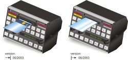
| Card
Release Source | RM420-013 Chip Card Reader
| Logic Source | You can select
an arbitrary logic source, mostly the key for ejecting the chip
card “Eject Card” (for card readers with electromechanical ejection). Production until May, 2003, RM420-013 produced from
June 2003 do not have an electromechanical ejection.
|

![[Note]](../pics/note.gif)