Table of Contents
For each Device, there is a node Console in the project tree. If you select it, you can configure the Console of the Device. In order to do that, you first need to select the modules in the configuration window and then assign their keys to the desired functions and labels.
![[Important]](../pics/important.gif) | Important |
|---|---|
The modules RM420-027 (Talkback Panel), RM420-078 (8 LCD Pushbutton Panel) and RM420-079 (16 LCD Pushbutton Panel 1U/19“) are currently supported by the Toolbox4.5 software. Use this software to configure all available functions. More information about their functionality and interoperation with the RM4200D will be available soon. For the module RM420-018 (Router Control Panel) there is a special configuration software. | |
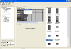
When the node Console is activated, two tabs appear on the right side of the program window. (see figure 40: Configuring the Console. ):
On the tab Console you can select the necessary modules and insert them into the chosen mounting frames.
In the tab Keys you can assign the keys of the Console the desired functions and attach labels to them.
You can configure the Console of RM4200D per Drag and Drop using the mouse. Simply select the module on the right panel of the dialog and drag it to the desired position in the mounting frame.
If you want to insert a further mounting frame, move the cursor over the “tab” on top of the Console pane and select the contextual menu by right-clicking with the mouse. With the command Add Console you can now add a new mounting frame. This way, you can create up to six different Consoles. (see figure 40: Configuring the Console. )
With the command Remove Console you can remove a mounting frame after confirming your decision. If you want to change the name of the frame, use the command Rename Console.
![[Note]](../pics/note.gif) | Note |
|---|---|
The graphic visualisation of the Consoles is only important for printing the views of the mixing desk; otherwise, they just visualise the Console surface for the user of the software. For the configuration itself, the position of the modules in the mounting frame is of no importance at all. | |
If there are already modules in the mounting frame, you can open a contextual menu by right-clicking on the slots. If you click on an existing module, you can “cut it out” with the command , and use to move it to another slot afterwards. If you have already defined functions and labels for the keys of the module, these are transferred to the new slot, too. The command works similar – it copies the module to the clipboard without removing it from its slot.
Using the contextual menu, you can delete modules with the command or print a view of the modules already arranged with the command . This function is identical with the option Modules Layout in the printing dialog of the command from the menu. (see Print)
When inserting the Module, please watch out for the following special features:
Fader Overbridge modules can only be used in connection with a Fader Module. You can configure only one Overbridge Module per Fader Module. The Overbridge Modules RM420-023 and RM420-028 can only be configured if you have previously inserted a Fader Module RM420-029 or RM420-020 below. If this is not the case, the message Fader Overbridge can only be used in combination with fader modules is displayed.
The Studio Panel RM420-011 is created as desktop device and therefore needs no mounting frame. Thus, you can not “drag” it to the Console already containing other modules. If you do so, the message: The Studio Panel requires its own console! appears. You can insert the module into an empty Console only. If there is none available, you first have to create one before inserting the Studio Panel.
If you put the empty modules RM420-022 and RM420-022-O into the Console, this is only influencing the printout and the display view of the Console.
When inserting Fader Modules of the types RM420-020 or RM420-029, DSP resources for the Input processing are assigned automatically. One stereo processing is necessary for each fader, the bars for the DSP processing change according to the number of inserted Fader Modules. Please consider that here only ”empty“ DSP processings and the necessary Routing Channels on the bus system are assigned. If you assign actual DSP functions to a Fader Channel, the DSP load increases again.

![[Tip]](../pics/tip.gif)