Table of Contents
- 2.1. File Menu
- 2.2. View Menu
- 2.3. Transfer Menu
- 2.4. Options Menu
- 2.5. Help Menu
This section describes the commands and dialogs of the Toolbox4 software.
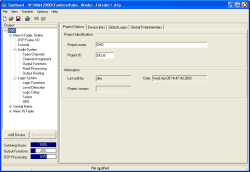
You can start the program by double-clicking on the file Toolbox4.exe. After that, the main program window opens as in the following figure:
This command creates a new project and generates a new project ID using a random number generator. The project is empty and does not contain any devices yet.
You can also execute this command by clicking on the icon
in the tool bar.
Any project file that is already open can be saved before creating a new file.
![[Note]](../pics/note.gif) | Note |
|---|---|
Only one project file can be edited at a time. | |
This command opens a project file.
You can also execute this command by clicking on the icon
in the tool bar. The keyboard shortcut for this command is Ctrl+O.
Any project file that is already open can be saved before creating a new file.
This command saves the open project file.
You can also execute this command by clicking on the icon
in the tool bar. The keyboard shortcut for this command is Ctrl+S.
This command saves a copy of the current project file. In the Save dialog box, the program suggests the name “filename_copy.ddp”. After saving the copy, the currently open project file “filename.ddp” remains open for further editing.
![[Tip]](../pics/tip.gif) | Tip |
|---|---|
This command allows to save different intermediate states of a project file as a backup. | |
The current project file is saved either under its previous or under a new file name. In the Save dialog box, the program suggests the previous name “filename.ddp”. After saving, the project file is edited under the new name.
It is possible to save the configuration of individual Devices in a file. (see Extract Device to File) With the command you can select a Device file (with the extension .ddf) and overwrite a device in the project with its content.
This function is only available if a Device is selected in the project tree. Otherwise, it is disabled.
![[Warning]](../pics/warning.gif) | Warning |
|---|---|
The configuration of a Device already available in the project is overwritten with this command – it cannot be undone! Therefore, the program shows a confirmation dialog before you can select a Device file. If you confirm this selection of the file in the Open dialog box, the current configuration of the device is finally replaced! If in doubt, in advance save the old configuration of the Device using the command . | |
This command allows you to transfer a Device configuration from one project to another. To transfer the data, use the following steps:
Save the already existing Device configuration in the relevant project. There, select the desired Device in the project tree and save its configuration in a file using the command.
Create an empty Device in the new project. In order to do that, press the button under the project tree or use the contextual menu in the project tree.
Select the new Device with the mouse, then select the menu command . Select the file that you created in step 1. Now you have copied the configuration of the Device from a previous in the new project.
![[Important]](../pics/important.gif) | Important |
|---|---|
When copying Device configurations, watch out for already defined Global Functions. The values for Global Logic and Global Potentiometers may be overwritten with information from the Device file. | |
This command saves the configuration of a Device as file with the extension .ddf. The name of the file can be selected.
This function is only available if a Device is selected in the Project tree. Otherwise, this menu option is disabled.
You can use this command to print Device information on paper.
You can also execute this command by clicking on the icon
in the tool bar.
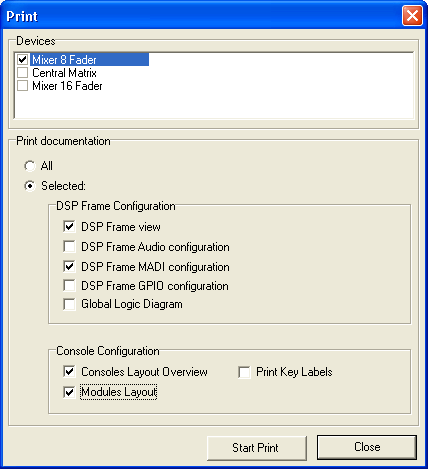
In the pane Devices you select, which Devices the output will be generated for.
In the pane Print documentation you can select, which parts of the documentation are to be printed for the selected Devices.
The option All prints the whole documentation for the selected Devices.
Alternatively, with the option Selected you can select the following options for printing:
DSP Frame view: View of the DSP frame with all configured cards.
DSP Frame Audio configuration: List of the Audio configuration with assigned labels, slot numbers, connector numbers and further options. In order to keep the list well-structured, there are no MADI modules included.
DSP Frame MADI configuration: List of the MADI configuration with assigned labels, connector numbers and further options. In order to keep the list well-structured, there are only MADI modules included.
DSP Frame GPIO configuration: List of the GPIO configuration with assigned labels, slot numbers and connector numbers.
Global Logic Diagram: Overview of the Global Logic functions created by the Device (Global Logics).
Console Layout Overview: View of the whole Console on one or more sheets, according to the number of assembly frames.
Modules Layout: View of all Control Modules contained in the configuration, each module printed on one sheet.
Print Key Labels: Printout of all key labels contained in the configuration on one or more sheets. For printing, presentation transparencies should be used in a suitable printer. The printed labels can be cut and inserted into the key caps.
This command outputs the configuration of a Device as text file. The file is formatted in CSV format (comma separated value). This format can be read by different text processors and spreadsheet programs. Thus its is possible to easily import configuration data for further documentation. The file contains different information of the Device configuration, including labels and numbering of the configured audio channels and GPIOs, defined Fader Channels and a list of the used internal signals.
This command is only available if a Device is selected in the project tree. Otherwise, it is disabled.

