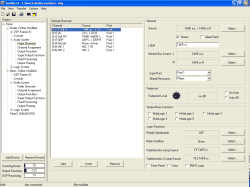
You reach the dialog by navigating in the project tree, as a further sub branch underneath the branch Audio System.
Here, the Fader Channels are configured that can be switched on to faders. Up to 150 Fader Channels per Device can be configured. Each Fader Channel has an assigned audio source and further features that are configured here, too.
![[Note]](../pics/note.gif) | Note |
|---|---|
To be able to really put an audio source on a “physical” fader, this audio source must be first defined as Fader Channel. Then, you can assign he defined Fader Channel in the dialog Channel Assignment to the faders themselves. | |
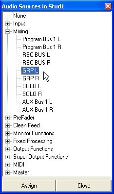
All audio signals available on the TDM bus can be used as sources, mostly input signals are assigned. If you assign a program bus to a Fader Channel, you can create a group. If necessary, a source can be also assigned to several Fader Channels.
In addition, there are 16 MIDI sources as special functions that do not have an audio signal. These are used to remotely control certain editing systems using the fader.
In this pane of the dialog you can define new channels and modify existing ones. The list displays the defined channels; in the column Channel you find the item number of the Fader Channel and its label. The displayed number of a channel, e.g. CH42 is for information only and has no influence on the further configuration. You need it only if you want to use certain functions in scripts, where the functions refer to Fader Channels. In such a case, this number is used in hex format within the script. (see also Scripts – Controlling Special Functions with Scripts )
In the column Source the assigned audio source is displayed, in the column Pool you find the assigned Input Pool. If no pool is assigned to the fader, this column remains empty.
At the same time, the order of the Fader Channels determines the order in which the channels are stored in the assigned Input Pools. If several Input Pools are used, the order follows from up to down separately for each Input Pool. The Fader Channels belonging to an Input Pool do not have to be arranged block wise in the list. If you want to change the order of the list entries you can simply do that by Drag&Drop.
In order to create a new Fader Channel, click on the button . This automatically opens the Audio Sources Window which is then active. Now select the desired audio source and assign it by either double clicking or clicking on the button .
With the button you can insert a new Fader Channel above a marked list line, with you can delete the entry. If a total number of 150 Fader Channels is defined, the functions and cannot be executed any more. The functions and can also be used with the contextual menu inside the list.
For a Fader Channel, you can configure the following general options:
| Option | Description | ||||
|---|---|---|---|---|---|
| Source | The audio signals (mono or stereo) that serve as inputs for the Fader Channel. You can change the audio source of an already existing Fader Channel by double clicking on the marked line in the list or by clicking on the button . Drag&Drop from the Audio Sources Window works, too. | ||||
| Label | Name of the channel. At the first assignment of an input to a new Fader Channel, the first 8 characters of the name of the audio source are automatically kept. This can be changed here later. Please note that for the Fader Module RM420-020 only 4 characters are available in the display, for the RM420-029 8 characters are displayed with a line wrap after 4 digits. Spaces are counted as characters. | ||||
| Stereo | The channel is mono or stereo. The feature mono or stereo is also automatically taken over from the assigned source; it can be changed later on with the checkbox stereo.
| ||||
| Clean Feed | This checkbox assigns a corresponding Clean Feed signal to the channel. Please note that a summing bus is consumed as resource and inserted in the list under Audio System/Mixing Functions. (see also Mixing Functions – Configuring Internal Buses ) Clean Feeds in a RM4200D are always assigned to a Fader Channel. If this assignment is unwanted, you can use AUX and Program buses for setting up Clean Feed signals. | ||||
| Global Pool | When you tick this checkbox and if you have defined a Global Pool Line, you can access the audio sources from the remote Device. The Audio Sources Window will list the sources of the remote Device instead of the local ones. (see also Global Pool Line as Source for a Fader Channel) | ||||
| Monitor Bus Source | If in the Fader Module keys are defined with the function Monitor Bus Control, you can configure the signal to be monitored for this function using the buttons . As preset, the source of the Fader Channel itself is assigned; but also the Clean Feed belonging to the Fader Channel or any other signal can be chosen. Channel related alternating monitor keys can work independently or in connection with monitor key sets in a Control Module. The monitor key set can e.g. be extended with this function to Fader Modules and is independent from the PFL function. (The function Monitor Bus Source is rarely used.) | ||||
| Input Pool | Use the pop up menu to assign one Input Pool to the selected Fader Channel. In this menu only the Input Pools configured under Audio System/Input Pools are displayed, also the entry None. Use the latter if you want to lock a Fader Channel to a certain “physical” fader. If you do not want to use the Fader Channel in the pool without deleting it, you have to assign None, too. (see also Input Pools – Properties) | ||||
| Global Resource | Use this menu to assign a configured Global Resource to the Fader Channel. If you have configured a key with the function Resource in the fader strip, this key will show you the state of the resource. If it shows the key color ON, the local Device owns the resource. You can also use this key to request an already owned resource, to cancel such a request, to release a resource or to take it over. (see also Fader Modules and List of Functions) | ||||
The fader starts can be used as Logic Source for arbitrary functions. In most cases, they are directly routed to the GPOs or control a red light signal using logic functions.
![[Note]](../pics/note.gif) | Note |
|---|---|
If you control a GPO with the fader start, during the configuration of the GPO you have to determine, whether the switching signal should be generated as level change (Level) or impulse (Start/Stop Pulse). (see also GPOs - General Purpose Outputs) | |
You can select the following options for the faderstart of the selected channel:
| Option | Description | ||||
|---|---|---|---|---|---|
| Faderstart Level | Level value from which the fader start is active. -oo is set as a preset, as the lowest stop. You can adjust the level in a range between -oo and -10dB in steps of 10dB. The setting refers to the scale of the Fader Module and activates the corresponding Logic Source Faderstart/FS <FaderChanName> when exceeding the set value. | ||||
| On Start | The logic source Faderstart/FS <FaderChanName> is only activated over the key function Channel On/Off , not when moving the fader.
| ||||
| Auto Off | When closing the fader, the channel is switched OFF automatically.
| ||||
Here you can assign which Mute Logics are activated when opening a fader. In most cases, this assignment is used to mute loudspeakers when opening microphone channels. You can control up to five Mute Logics, to do this, activate the corresponding checkboxes.
You can change the names of the different Mute Logic buses under Audio System/Mute Logics. (see Mute Logics )
The assignment of the corresponding Mute Logic to the output signals of the RM4200D is defined under Audio System/Output Routing. (see Output Routing )
Here you determine how the selected Fader Channel is coupled with the Logic System of the RM4200D. In detail, you can configure the following options:
| Logic Function | Description | ||||
|---|---|---|---|---|---|
| Ready Signalisation | The Fader Overbridge Modules RM420-023 and the Fader Modules RM420-029 contain a fixed LED labelled READY. Here you can determine with which Logic Source this display is switched on. The Logic Source is preset to OFF; in this case, the display is switched on at closed fader. If you do not want READY to shine, you have to configure None. For modifications click on the button , this opens the Logic Sources Window and activates it. Assign the desired Logic Source with the button , per double click or Drag&Drop. Application example: Over GPIs, status signals of playout devices can be displayed. External keys connected using GPIs can display signals triggered by the presenter at the microphone channels. | ||||
| Mute Condition | Here you can assign which Logic Source can trigger muting of the Fader Channel on activation. None is preset, the channel is not muted. For modifications click on the button , this opens the Logic Sources Window and activates it. Assign the desired Logic Source with the button , per double click or Drag&Drop. Application example: Over GPIs, external cough keys can be connected.
| ||||
| Faderfunction Lamp Source | If in the Fader Module, you assigned a Fader Function to a key, here you can configure, which Logic Source makes the LED of this key light. (see function Fader Function) The preset Logic Source is the fader function of the selected Fader Channel itself (Fader Function/FF <FaderChName>). In this case, the key is lit when the fader function is active. For modifications click on the button , this opens the Logic Sources Window and activates it. Assign the desired Logic Source with the button , per double click or Drag&Drop. Application example: As talk key for Clean Feeds, talk key for headphones that are assigned certain microphones (programming over Output Functions), Faderstart On/Off for input Devices (programming over logic functions). | ||||
| Faderfunction Lamp Source 2 | Same function as Fader Function Lamp Source. | ||||
| Timer Reset | If you assigned Timer Function/Timer Fader to a key in a Control Module, the timers 1...12 can be reset when opening the fader. If you click in this checkbox, the selected Fader Channel triggers the reset. (see function Timer Function) | ||||
| Voice | If this checkbox is switched on, the Fader
Channel activates the Logic Source System Functions/Voice. Application example: You can assign the Logic Source Voice to a GPO, thus using it as external voice/music identification. | ||||
| PGM1 Logic | If this checkbox is switched on, the Fader
Channel activates the Logic Source System Functions/PGM1,
but only if the channel is switched on the program bus
1 at the same time. Application example: The Logic Source PGM1 Logic can be used externally using a GPO as Air Check Record Start – only open faders start recording that are switched on to program bus 1 and configured in this function. | ||||


![[Important]](../pics/important.gif)