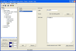
By using scripts, you can control the internal functions of the RM4200D directly with commands sent over the CAN bus. This way you can also use functions that can not be directly configured as key functions but are supported by the firmware of the RM4200D. Scripts are started by an assigned logic function as soon as this outputs a rising edge. Then the script sends a preset series of commands to the CAN bus.
You can configure up to 100 scripts with a total number of up to 1000 commands. The scripts are processed from top to bottom. The lines inside a script are processed with a delay of 40ms to avoid system overloads.
You find the RM4200D CAN Bus commands in the volume “DHD RM4200D Protocol Description” of this manual. In addition, you can select and copy currently executed commands in the window Maintenance. To do that, use the command in the menu of the window Maintenance. (see also Enable CAN Protocol ()
You can insert scripts in the list Scripts by using the button or remove them with the button . Both functions are also available in the contextual menu.
If you have highlighted an entry in the list Scripts you can configure the corresponding script in the pane Edit Script of the dialog:
First name the script in the field Label. The name can be up to 10 characters long.
Now click on the button , to open or activate the Logic Sources Window. Select the logic source that is to start the script and assign it under Select Condition. This can be done either with the button , a double click on the desired Logic Source or using Drag&Drop.
Now enter in the pane Edit Script a list with the desired commands. Each line may contain only one valid RM4200D CAN bus command.
Finally, click on the button , to compile the entered commands into the internal data structures. For larger scripts, this process can last some seconds.
![[Important]](../pics/important.gif) | Important |
|---|---|
Before saving the script or leaving the script window using the button, you have to check whether the entered script is correct. This check is compulsory, since incorrect commands (because of typing errors) can otherwise cause unexpected malfunctions. | |
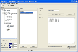
The following example uses an external control signal at a GPI to switch on the faders 1 to 4. This can be used to e.g. switch on the microphones in a studio using an external key.
The following table contains some further examples for CAN bus commands:
| RM4200D CAN Bus command | Function |
|---|---|
| 11160000,0 | PFL Reset (for all switched on PFLs) |
| 11020000,3,10,01,01 | Fader Channel 1 ON |
| 11020000,3,10,02,01 | Fader Channel 2 ON |
| 11020000,3,10,03,01 | Fader Channel 3 ON |
| 11020000,3,10,04,01 | Fader Channel 4 ON |
| 11020000,3,10,01,00 | Fader Channel 1 OFF |
| 11020000,3,10,02,00 | Fader Channel 2 OFF |
| 11020000,3,10,03,00 | Fader Channel 3 OFF |
| 11020000,3,10,04,00 | Fader Channel 4 OFF |
| 11000000,6,40,02,01,00,40,03 | Monitor Bus 1 switched on to Program Bus 1 |
| 0103FFFF,0 | System-Reset |

