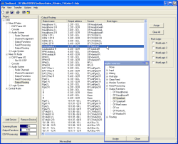
You find the menu by navigating in the project tree as further sub branch below the branch Audio System.
Here, the desired audio channels of the TDM bus are assigned to the I/O-Modules of the RM4200D. This Output Routing is part of the configuration thus being fixed.
If you want to change the routing flexibly during operation, other internal functions like routing with keys, scripts or rotary monitor selectors are available. In addition, you can also use the routing software RM420-550.
![[Important]](../pics/important.gif) | Important |
|---|---|
Output Routing is carried out independently from the output configuration under DSP Frame I/O, generally in mono. This means that you have to configure it separately for both channels of a stereo signal. You can configure the output routing independently from the corresponding type of output (analog, digital, MADI) for each output without any limitations. | |
The following signals can be routed:
Audio channels available on the internal TDM bus system: Inputs, Mixing (sums, groups, AUX buses), Pre Fader (Fader Channels after Input Processing), Clean Feeds, Monitor Functions (only PFL), Fixed Processing, Output Functions.
Internal “virtual” Audio sources: Monitor Functions (Monitor Buses 1 - 6), Routing (Number 1 to 768).
For routing, first select the desired output in the list Output Routing. Double click on the entry or use the button , to open the Audio Sources Window and to activate it.
Now select the desired audio source and assign it with the button or by double clicking it. You also can assign an audio source by dragging and dropping it directly on to the entry of the desired output in the list Output Routing.
For each output, the following information is displayed in the list Output Routing:
Output name: The name entered under DSP Frame I/O, for stereo outputs a row for each channel (left and right).
Output address: The address preset by the system after the unified scheme: <Slot number>.<Plug number>.<Channel number per plug>.
Source: Routed audio source, None means muting.
Mute Logic: Mute Logics assigned to the output.
Here you assign which Mute Logics can mute the selected output. Use the checkboxes in the pane Mute Logics to assign the corresponding functions. Under Fader Channels you determine which faders activate which Mute Logics. (see also Output Mute Functions)
In most cases, this function is used for microphones and loudspeakers that are installed in the same room. The loudspeakers are switched off as soon as the microphone faders open.
This is a special function of the Digital-In/Out Modules RM420-111.
![[Important]](../pics/important.gif) | Important |
|---|---|
CS Routing may only be active if a Router Control Panel RM420-018 that is configured accordingly or a Yellowtec Intellimix is connected to this output. Also, the input assigned to the output must be connected to the RM420-018 or the Intellimix using the same connector! | |
These two Devices can control over the Channel Status Bits of the assigned input received by the RM4200D, which audio sources of the TDM bus are routed to the corresponding output. To achieve that, in the AES/EBU data stream, the ASCII fields Source and Destination of the Channel Status Data are used for transferring the corresponding address.

![[Warning]](../pics/warning.gif)