Table of Contents
- 5.1. Overview
- 5.2. Console - Choosing Modules
- 5.3. Frame I/O - Configuring the DSP Frame
- 5.4. Mod. Options - Configuring Module Options
- 5.5. Func keys - Configuring Function Keys
- 5.6. Talkback
- 5.7. Various - Configuring Level Meters and Clean Feeds
- 5.8. Connection - Configuring the Network Identity
- 5.9. Protocol - Monitoring the CAN-Bus and Sending Commands
You use the Configuration Mode of the RM2200D software for the initial setup of new systems and maintenance tasks on running systems.
You activate the Configuration Mode by clicking on the button which is located bottom right next to the orange DHD logo. The configuration dialog with various options appears. You can close this dialog box either by clicking the Windows close box in the top right corner window or by using the button in the bottom right corner of the dialog. (See the following screenshot.)
The configuration dialog contains several tabs which activate subpanes for the different options. The subpanes are:
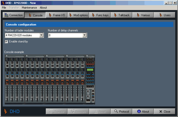
Console. Here you select the number of modules for the mixing desk. You can also set the password to protect access to the configuration dialog. (see Console - Choosing Modules)
Frame I/O. Use this dialog to select the modules for the DSP frame and to set up the properties of these modules. (see Frame I/O - Configuring the DSP Frame)
Mod. options. You can use the settings in this dialog to change the way the fader modules and the Master Control Module of the mixing desk work. (see Mod. Options - Configuring Module Options)
Func. keys. Here you set up how the push button keys on the mixing desk work. (see Func keys - Configuring Function Keys)
Talkback. In this dialog you configure the talkback system of the RM2200D. (see Talkback)
Various. Use this dialog to select the audio sources for the internal level meters in the Master Control Module and for the graphical meters in the RM2200D software. You can also setup the clean feed options here. (see Various - Configuring Level Meters and Clean Feeds)
Connection. Use this dialog to connect to a RM2200D system. If necessary, you can also change the IP address of the device here. (see Connection - Configuring the Network Identity)
Protocol. Use this dialog to monitor the activity on the CAN bus and transmit single commands from the software. Besides, you can control the way the system log works from here. (see Protocol - Monitoring the CAN-Bus and Sending Commands)
If you connect to the RM2200D for the first time, use the dialog Connection to do so. After that, the software keeps the connection alive. Even if you quit the software and restart it later, it will keep the information and try to connect to the last known RM2200D. You can monitor the state of the connection with the two LED icons on the right side of the Small Screen Display. (see also Connection - Configuring the Network Identity)
![[Important]](../pics/important.gif) | Important |
|---|---|
If you can not connect to the RM2200D, check cables and network configuration. Also make sure, you are not running any other DHD software on your computer simultaneously. If you do so, you could experience problems receiving data from the RM2200D. | |
The RM2200D software uses special data structures to store the changes you make to the configuration. These data structures are called Configuration Dataset or Config for short. Usually, a Config is stored within the communications controller of the RM2200D. Using the RM2200D software, you can download it from there, edit it and finally upload your changes back to the DSP frame.
Every RM2200D is shipped from DHD with a standard Config preloaded. This Config is also on the CD included with the RM2200D. You can use it as a starting point for your own changes.
![[Important]](../pics/important.gif) | Important |
|---|---|
Please note, that you need to upload a changed Config back to the RM2200D for the changes to take effect. There is no “Auto-update” function. | |
You can also use the commands in the to create a new Config, to save the current Config to disk or to open a saved Config file. It is good practice to keep backups of your Config files and give them descriptive names.
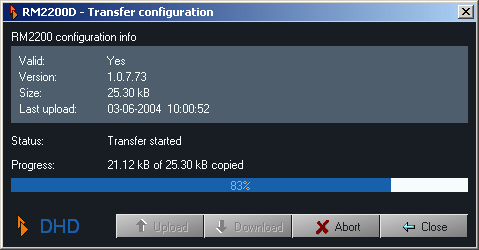
To transfer a Config, you can either click the button at the bottom of the configuration dialog or use the command from the menu . The following dialog appears:
In the upper half of the dialog you can read detailed information about the current Config. In the lower half you can start the up- or download and monitor the progress of the data transfer. Once the transfer has finished, use the button to dismiss the dialog.
![[Warning]](../pics/warning.gif) | Warning |
|---|---|
If you are editing a new Config or changing an existing one, make sure you save your current edits to disk before attempting any transfer operations. Currently the software does not double-check for unsaved data and under certain conditions it may discard unsaved edits. A future version of the software will fix this issue. | |
The “operation system” of the RM2200D runs in the RM220-950 controller module. This special software is called Firmware and stays resident in the flash memory of the controller, even when the RM2200D is switched off. Usually, you do not need to worry about the firmware, it just works in the background. However, DHD may release a new firmware version from time to time. This new version may fix bugs or implement new functions.
![[Important]](../pics/important.gif) | Important |
|---|---|
If your RM2200D system runs fine even with an older firmware version, do not change it without need! Only update if the new version fixes some bugs which affect you or if told so by DHD support. Also keep in mind, that the version of the firmware and the version of the RM2200D software are closely related. A certain firmware version may require a certain version of the software and vice versa. If you use mismatching versions, you may run into problems! Before changing your setup, be sure to check the RM2200D website for details at:www.rm2200d.com | |
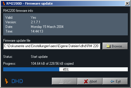
To update the firmware, choose the tab Frame I/O and click the button . The following dialog opens:
In the upper half of it you can read detailled information about the firmware version currently running in the RM2200D. To update the firmware, use the button to locate the updater file. Next, click the button to start the upload . This process will take some seconds, the progress bar will show the current status. When the upload completed successfully, you need to reset the DSP frame to activate the new firmware. A confirmation dialog appears. Click the button there and the DSP frame will reset itself.
![[Warning]](../pics/warning.gif) | Warning |
|---|---|
Do not reset the DSP frame while the RM2200D is used or even On Air! Although you can not damage the system, a reset loads the Basic Setup 0 as defined in the Full Screen Display. This setup can be different from the current state of the RM2200D and therefore affect the audio output of the system in unpredictable ways. (see Full Screen Display) | |
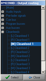
Audio sources are all signals that are available within in RM2200D. When you configure the system, you often need to assign audio sources to certain things - as sources for output connectors, as talkback signals, clean feed sources etc. In all these cases, you use the Audio Sources window to select the desired signal.
The Audio Sources window is divided in several sections. The signals have names, they are either fixed or (in the case of input signals) you can change them in the dialog Frame I/O of the RM2200D software.
The available audio sources are divided into the following sections. Stereo signals are split in left (“L”) and right channel (“R”). Mono signals - like microphone inputs - are labeled “M”:
| Section | Signals included |
|---|---|
| Mute | This is the “No Signal” signal. If you select it as audio source, the signal will just be silence. |
| Audio Inputs | These are all input signals connected to the DSP frame. The signals show the labels they were assigned in the dialog Frame I/O. However, the inputs of the RM220-228 Analog Input Selector module are not available.(see also RM220-228 Analog In Selector Module) |
| Pre-fader signals | For each fader in the mixing desk, you can access the signal of its currently assigned input channel. This channel is taken before the fader affects the signal level! Please note, that the signal will change instantly, if you assign another input signal to the fader channel! |
| Cue bus | This is the signal currently on the cue bus. It is available both in mono and stereo. |
| Program busses | The two program bus signals are available here, both in mono and stereo. |
| Aux busses | The two Aux bus signals are available here, both in mono and stereo. |
| Cleanfeeds | The four clean feed signals are available here, both in mono and stereo. |
| Monitors | This category contains the signals of all five
monitor busses. The signals are available in stereo. If the label is
just Monitor <No.>, the signal is not level
controlled. The other attributes have these meanings (not all of
them are available on all monitor signals):
|
| Monitor selector inputs | These are the four monitoring inputs of the RM220-228 Analog In Selector Module. They are available within the monitoring system only and only if the module is contained within the DSP frame. (see also RM220-228 Analog In Selector Module) |
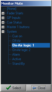
Logic sources control many of the functions within the RM2200D. A logic source is a condition which is either active (“true”) or inactive (“false”). If you need to assign a logic source to a certain function, you need to select it from the Logic Sources window.
The Logic Sources window is divided into these sections:
![[Tip]](../pics/tip.gif)
