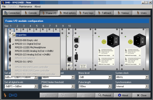
Use this dialog to configure the modules in the DSP frame, to update the firmware and to reset the DSP frame.
To assign a module to a slot, right-click on the slot and choose the desired module from the context menu. To change the settings of a certain module, double-click on it. This will open the appropriate configuration dialog for the choosen module.
![[Tip]](../pics/tip.gif) | Tip |
|---|---|
If you let the mouse pointer rest over any module in the DSP frame, it will display its number as a tool tip. | |
To update the firmware, click the button . Choose the file with the new firmware and upload it to the DSP frame. (see also Managing the Firmware)
To reset the DSP frame, click the button . A confirmation dialog appears. If you click yes there, the DSP frame resets itself.
![[Warning]](../pics/warning.gif) | Warning |
|---|---|
Do not reset the DSP frame while the RM2200D is used or even On Air! Although you can not damage the system, a reset loads the Basic Setup 0 as defined in the Full Screen Display. This setup can be different from the current state of the RM2200D and therefore affect the audio output of the mixer in unpredictable ways. (see Full Screen Display) | |
Below the picture of the DSP frame there are two rows with pop-up menus, which control the following options:
Set all analog levels. Here you adjust the value of all analog levels with respect to the internal “0 dB” reference level.
Set all digital levels. Here you adjust the value of all digital levels with respect to the internal “0 dB” reference level.
PGM1 limiter threshold. Adjust the threshold for the limiter of the “PGM1” signal from -20 dBint to +20 dBint. To turn the limiter off, choose option “Off”.-
PGM2 limiter threshold.Adjust the threshold for the limiter of the “PGM2” signal from -20 dBint to +20 dBint. To turn the limiter off, choose option “Off”.-
Mono level. Use this pop-up menu to control how all internal mono summing functions work. This affects mono signal generation for monitoring and mono busses. You can select values from 0 dB to -6 dB in 1 dB steps.
Pulse length. This setting controls the length of the GPO pulse outputs. The pulse length can vary between 50 ms and 500 ms.
System clock. Select the frequency of the internal system clock here: either 44.1 kHz or 48 kHz.
Synchronisation. Select the source the RM2200D should synchronize to. Use Internal for the internal clock source or any available digital input.
Digital In/Out/GPIO module, 8 channels (4 stereo), 4 RJ45 connectors. The module provides:
4 AES3/EBU/SPDIF inputs.
4 AES3/EBU/SPDIF outputs.
4 async. input sample rate converters.
4 general purpose inputs, TTL.
4 general purpose outputs, open collector.
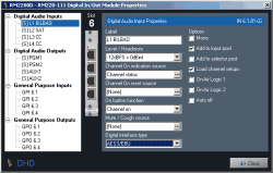
Label. Enter a descriptive name for the input here. This name will appear in all other parts of the software to identify this input.
Level/Headroom. Adjust the headroom for this input between -12 dBu and +18 dBu. This value overrides the global setting in the dialog Console. (see also Console - Choosing Modules)
Channel On indication source. Select here, which logic source lights the “Channel On” indicator on top of the fader. Default value is Channel Status, displaying the current status of the fader. If you want to change it, click the button and select any other logic source from the Logic Sources window.
Channel On reset source. Select here, which logic source switches the channel off when activated.
On button function. Use this option to control the function of the “ON” button on top of the fader. These values are available:
Channel on. Audio is switched on if both the button “ON” is active and the fader is open.
On start. Audio is switched on, when the button “ON” is activated, regardless if the fader is open or not.
Fader start on/off. Audio is switched on as soon as the fader is opened. The “ON” button switches only the fader start signal on and off.
Mute/Cough Source. Select here, which logic source mutes the input. Click the button to select any other logic source from the Logic Sources window.
Digital interface type. Set this option according to the digital device you want to connect to this input. Available options are AES3/EBU and S/PDIF.
Mono. Check this box when using mono signals as inputs. If this option is active, the display of the audio inputs in the left tree display contains two mono inputs instead of one stereo input. Mono inputs have a label “[M]” in front of the entry, stereo inputs are labeled“[S]”. Also, the two popup menus for output routing change to one for each channel.
Add to input pool. If you check this box, the input is available as fader input in the Input Pool of the RM2200D. (see also Input Pool, Fixed Faders and Selectors)
Add to selector pool. If you check this box, the input is available as a monitor input in the Selector Pool. (see also Input Pool, Fixed Faders and Selectors)
Load channel setup. If you check this box, you allow the user to load channel setups into this channel. (see also Using Setups)
On-Air Logic 1. If you check this box, opening the fader will activate the logic source On-Air logic 1. You can use this for example to switch on the red light in the control room.
On-Air Logic 2. If you check this box, opening the fader will activate the logic source On-Air logic 2. You can use this for example to switch on the red light in the studio.
Auto off. If you check this box, closing the fader will switch off the Channel On state when the fader is closed.
Label. Enter a descriptive name for the input here. This name will appear in all other parts of the software to identify this input.
Level/Headroom. Adjust the headroom for this output between -12 dBu and +18 dBu. This value overrides the global setting in the dialog Console. (see also Console - Choosing Modules)
Output routing audio source L. Select here, which internal audio signal is routed to the left channel of this output port. To change this setting, click the button and choose the desired audio signal from the Audio Sources window. (Left channel signals are labeled “[L]”, right channel signals are labeled “[R]”).
Output routing audio source R. Select here, which internal audio signal is routed to the right channel of this output port. To change this setting, click the button and choose the desired audio signal from the Audio Sources window.
Mono. Check this box when using this output for mono signals. If this option is active, the display of the audio outputs in the left tree display contains two mono outputs instead of one stereo output. Mono outputs have a label “[M]” in front of the entry, stereo outputs are labeled “[S]”. Also, the two popup menus for output routing change to one for each channel.
On-Air Logic 1. If you check this box, the output signal will be muted when the logic source On-Air logic 1 becomes active. You can use this for example to mute loudspeakers when microphones are opened.
On-Air Logic 2. If you check this box, the output signal will be muted when the logic source On-Air logic 2 becomes active. You can use this for example to mute loudspeakers when microphones are opened.
CS Routing information. If you check this box, you enable a special feature called CS Routing to work with this channel.
![[Important]](../pics/important.gif)
Important You can enable CS Routing only if a properly configured Router Control Panel RM420-018 or a Yellowtec Intellimix is connected to this output. Also, the input assigned to the output must be connected to the RM420-018 or the Intellimix using the same RJ45 connector on a RM220-111 Digital In/Out/GPIO module.
These two devices can control which internal audio signals of the RM2200D are routed to the outputs of the RM2200D, which in turn are connected to their inputs. They use the Channel Status Bits of the AES/EBU data stream to tell the RM2200D on the input channel, which signal it should put onto the output channel. To achieve that, in the AES/EBU data stream, the ASCII fields Source and Destination of the Channel Status Data are used for transferring the corresponding address. Please note, that CS Routing only works for AES/EBU inputs and outputs sharing the same RJ 45 socket!
Label. Enter a descriptive name for this GPI here. This name will appear in all other parts of the software to identify this input.
Level. Select the option Normal to activate the GPI with a positive voltage. Choose option , if you want the GPI to activate when the input voltage is near zero.
Label. Enter a descriptive name for this GPO here. This name will appear in all other parts of the software to identify this output.
Type. Select the kind of output the GPO gives when activated. These options are available:
Normal. The GPO carries a positive voltage when activated.
Inverted. The GPO carries a voltage near zero when activated.
Pulse on. The GPO gives a pulse when activated.
Pulse off. The GPO gives a pulse when deactivated. (see also Frame I/O - Configuring the DSP Frame)
Output routing logic source. Use this setting to assign an internal logic source to the choosen GPO. Click the button to select any other logic source from the Logic Sources window.
Analog Microphone In/Headphone Out/GPIO module, 4 channels (2 stereo), 4 RJ45 connectors. The module provides:
4 line inputs, electrically balanced, max. input level 18 dBu.
48 V phantom power, can be switched seperately for each microphone input.
2 stereo headphone outputs.
2 general purpose inputs, TTL with internal pull-up resistor.
2 analog control inputs (ACI).
4 general purpose outputs, open collector.
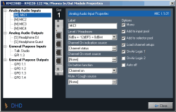
Label. Enter a descriptive name for the input here. This name will appear in all other parts of the software to identify this input.
Level/Headroom. Adjust the headroom for this input between -12 dBu and + 18dBu. This value overrides the global setting in the dialog Console. (see also Console - Choosing Modules)
Channel On indication source. Select here, which logic source lights the “Channel On” indicator on top of the fader. Default value is Channel Status, displaying the current status of the fader. If you want to change it, click the button and select any other logic source from the Logic Sources window.
Channel On reset source. Select here, which logic source switches the channel off when activated.
On button function. Use this option to control the function of the “ON” button on top of the fader. These values are available:
Channel on. Audio is switched on if both the button “ON” is active and the fader is open.
On start. Audio is switched on, when the button “ON” is activated, regardless if the fader is open or not.
Fader start on/off. Audio is switched on as soon as the fader is opened. The “ON” button switches only the fader start signal on and off.
Mute/Cough Source. Select here, which logic source mutes the input. Click the button to select any other logic source from the Logic Sources window.
Mono. Check this box when using mono signals as inputs. If this option is active, the display of the audio inputs in the left tree display contains two mono inputs instead of one stereo input. Mono inputs have a label “[M]” in front of the entry, stereo inputs are labeled“[S]”.
Add to input pool. If you check this box, the input is available as fader input in the Input Pool of the RM2200D. (see also Input Pool, Fixed Faders and Selectors)
Add to selector pool. If you check this box, the input is available as a monitor input in the Selector Pool. (see also Input Pool, Fixed Faders and Selectors)
Load channel setup. If you check this box, you allow the user to load channel setups into this channel. (see also Using Setups)
On-Air Logic 1. If you check this box, opening the fader will activate the logic source On-Air logic 1. You can use this for example to switch on the red light in the control room.
On-Air Logic 2. If you check this box, opening the fader will activate the logic source On-Air logic 2. You can use this for example to switch on the red light in the studio.
Auto off. If you check this box, closing the fader will switch off the Channel On state when the fader is closed.
Label. Enter a descriptive name for the input here. This name will appear in all other parts of the software to identify this input.
Level/Headroom. Adjust the headroom for this output between -12 dBu and +18 dBu. This value overrides the global setting in the dialog Console. (see also Console - Choosing Modules)
Output routing audio source L. Select here, which internal audio signal is routed to the left channel of this output port. To change this setting, click the button and choose the desired audio signal from the Audio Sources window. (Left channel signals are labeled “[L]”, right channel signals are labeled “[R]”).
Output routing audio source R. Select here, which internal audio signal is routed to the right channel of this output port. To change this setting, click the button and choose the desired audio signal from the Audio Sources window.
Mono. Check this box when using this output for mono signals. If this option is active, the display of the audio outputs in the left tree display contains two mono outputs instead of one stereo output. Mono outputs have a label “[M]” in front of the entry, stereo outputs are labeled “[S]”. Also, the two popup menus for output routing change to one for each channel.
On-Air Logic 1. If you check this box, the output signal will be muted when the logic source On-Air logic 1 becomes active. You can use this for example to mute loudspeakers when microphones are opened.
On-Air Logic 2. If you check this box, the output signal will be muted when the logic source On-Air logic 2 becomes active. You can use this for example to mute loudspeakers when microphones are opened.
Label. Enter a descriptive name for this GPI here. This name will appear in all other parts of the software to identify this input.
Level. Select the option Normal to activate the GPI with a positive voltage. Choose option , if you want the GPI to activate when the input voltage is near zero.
Label. Enter a descriptive name for this GPO here. This name will appear in all other parts of the software to identify this output.
Type. Select the kind of output the GPO gives when activated. These options are available:
Normal. The GPO carries a positive voltage when activated.
Inverted. The GPO carries a voltage near zero when activated.
Pulse on. The GPO gives a pulse when activated.
Pulse off. The GPO gives a pulse when deactivated.
Output routing logic source. Use this setting to assign an internal logic source to the choosen GPO. Click the button to select any other logic source from the Logic Sources window.
Analog In/Out/GPIO module, 4channels (2 stereo), 4 RJ45 connectors. The module provides:
4 line inputs, electrically balanced, max. input level 18 dBu.
4 line outputs, electrically balanced, max. output level 18 dBu.
4 general purpose inputs, TTL.
4 general purpose outputs, open collector.
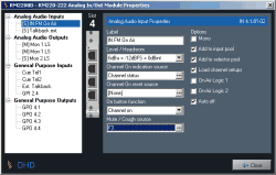
Label. Enter a descriptive name for the input here. This name will appear in all other parts of the software to identify this input.
Level/Headroom. Adjust the headroom for this input between -12 dBu and +18 dBu. This value overrides the global setting in the dialog Console. (see also Console - Choosing Modules)
Channel On indication source. Select here, which logic source lights the “Channel On” indicator on top of the fader. Default value is Channel Status, displaying the current status of the fader. If you want to change it, click the button and select any other logic source from the Logic Sources window.
Channel On reset source. Select here, which logic source switches the channel off when activated.
On button function. Use this option to control the function of the “ON” button on top of the fader. These values are available:
Channel on. Audio is switched on if both the button “ON” is active and the fader is open.
On start. Audio is switched on, when the button “ON” is activated, regardless if the fader is open or not.
Fader start on/off. Audio is switched on as soon as the fader is opened. The “ON” button switches only the fader start signal on and off.
Mute/Cough Source. Select here, which logic source mutes the input. Click the button to select any other logic source from the Logic Sources window.
Mono. Check this box when using mono signals as inputs. If this option is active, the display of the audio inputs in the left tree display contains two mono inputs instead of one stereo input. Mono inputs have a label “[M]” in front of the entry, stereo inputs are labeled “[S]”.
Add to input pool. If you check this box, the input is available as fader input in the Input Pool of the RM2200D. (see also Input Pool, Fixed Faders and Selectors)
Add to selector pool. If you check this box, the input is available as a monitor input in the Selector Pool. (see also Input Pool, Fixed Faders and Selectors)
Load channel setup. If you check this box, you allow the user to load channel setups into this channel. (see also Using Setups)
On-Air Logic 1. If you check this box, opening the fader will activate the logic source On-Air logic 1. You can use this for example to switch on the red light in the control room.
On-Air Logic 2. If you check this box, opening the fader will activate the logic source On-Air logic 2. You can use this for example to switch on the red light in the studio.
Auto off. If you check this box, closing the fader will switch off the Channel On state when the fader is closed.
Label. Enter a descriptive name for the input here. This name will appear in all other parts of the software to identify this input.
Level/Headroom. Adjust the headroom for this output between -12 dBu and +18 dBu. This value overrides the global setting in the dialog Console. (see also Console - Choosing Modules)
Output routing audio source L. Select here, which internal audio signal is routed to the left channel of this output port. To change this setting, click the button and choose the desired audio signal from the Audio Sources window. (Left channel signals are labeled “[L]”, right channel signals are labeled “[R]”).
Output routing audio source R. Select here, which internal audio signal is routed to the right channel of this output port. To change this setting, click the button and choose the desired audio signal from the Audio Sources window.
Mono. Check this box when using this output for mono signals. If this option is active, the display of the audio outputs in the left tree display contains two mono outputs instead of one stereo output. Mono outputs have a label “[M]” in front of the entry, stereo outputs are labeled “[S]”. Also, the two popup menus for output routing change to one for each channel.
On-Air Logic 1. If you check this box, the output signal will be muted when the logic source On-Air logic 1 becomes active. You can use this for example to mute loudspeakers when microphones are opened.
On-Air Logic 2. If you check this box, the output signal will be muted when the logic source On-Air logic 2 becomes active. You can use this for example to mute loudspeakers when microphones are opened.
Label. Enter a descriptive name for this GPI here. This name will appear in all other parts of the software to identify this input.
Level. Select the option Normal to activate the GPI with a positive voltage. Choose option , if you want the GPI to activate when the input voltage is near zero.
Label. Enter a descriptive name for this GPO here. This name will appear in all other parts of the software to identify this output.
Type. Select the kind of output the GPO gives when activated. These options are available:
Normal. The GPO carries a positive voltage when activated.
Inverted. The GPO carries a voltage near zero when activated.
Pulse on. The GPO gives a pulse when activated.
Pulse off. The GPO gives a pulse when deactivated.
Output routing logic source. Use this setting to assign an internal logic source to the choosen GPO. Click the button to select any other logic source from the Logic Sources window.
Analog Line In/Out/GPIO module, 4channels (2 stereo), 4 RJ45 connectors. The module provides:
4 line inputs, electrically balanced, max. input level 24 dBu.
4 line outputs, electrically balanced, max. output level 24 dBu.
4 general purpose inputs, TTL.
4 general purpose outputs, open collector.
(see also Configuring Analog Audio Inputs)
(see also Configuring Analog Audio Outputs)
(see also Configuring General Purpose Inputs)
(see also Configuring General Purpose Outputs)
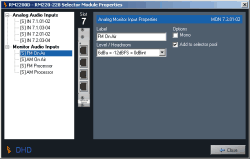
This is a special module. It contains 4 stereo line inputs which can be routed to fader channels using the Input Pool. Additionally, it contains 4 stereo line inputs which can be used for monitoring only.
![[Important]](../pics/important.gif) | Important |
|---|---|
Both the fader inputs and the monitor inputs work like a “classic” A,B,C,D input selector. You can only use one input signal as fader input at any time. Similar, you can only use one monitor input as source for the RM2200D monitoring system. You can not use the monitor inputs as signal sources for fader channels! Please note also, that you can only use one module RM420-228 in a RM2200D. This gives youe one selector on one fader and one selector in the monitoring section! Please consider these restrictions when designing your studio setup! | |
(see also RM220-228 Analog In Selector Module (stereo))
The module provides:
1 stereo input selector with A,B,C,D stereo inputs to route signals into fader channels.
1 stereo input selector with A,B,C,D stereo inputs to route signals into the monitoring system.
16 line inputs, electrically balanced, max. input level 18 dBu.
4 RJ45 connectors
Label. Enter a descriptive name for the input here. This name will appear in all other parts of the software to identify this input.
Level/Headroom. Adjust the headroom for this input between -12 dBu and +18 dBu. This value overrides the global setting in the dialog Console.
Channel On indication source. Select here, which logic source lights the “Channel On” indicator on top of the fader. Default value is Channel Status, displaying the current status of the fader. If you want to change it, click the button and select any other logic source from the Logic Sources window.
Channel On reset source. Select here, which logic source switches the channel off when activated.
On button function. Use this option to control the function of the “ON” button on top of the fader. These values are available:
Channel on. Audio is switched on if both the button “ON” is active and the fader is open.
On start. Audio is switched on, when the button “ON” is activated, regardless if the fader is open or not.
Fader start on/off. Audio is switched on as soon as the fader is opened. The “ON” button switches only the fader start signal on and off.
Mute/Cough Source. Select here, which logic source mutes the input. Click the button to select any other logic source from the Logic Sources window.
Mono. Check this box when using a mono signal as input. Please note, that the left channel is used as input, the right channel is not used. If this option is active, the display of the audio inputs in the left tree display contains a mono input instead of a stereo input. Mono inputs have a label “[M]” in front of the entry, stereo inputs are labeled “[S]”.
Add to input pool. If you check this box, the input is available as fader input in the Input Pool of the RM2200D. (see also Input Pool, Fixed Faders and Selectors)
Load channel setup. If you check this box, you allow the user to load channel setups into this channel. (see also Using Setups)
On-Air Logic 1. If you check this box, opening the fader will activate the logic source On-Air logic 1. You can use this for example to switch on the red light in the control room.
On-Air Logic 2. If you check this box, opening the fader will activate the logic source On-Air logic 2. You can use this for example to switch on the red light in the studio.
Auto off. If you check this box, closing the fader will switch off the Channel On state when the fader is closed.
Label. Enter a descriptive name for the input here. This name will appear in all other parts of the software to identify this input.
Level/Headroom. Adjust the headroom for this input between -12 dBu and +18 dBu. This value overrides the global setting in the dialog Console. (see also Console - Choosing Modules)
Mono. Check this box when using a mono signal as input. Please note, that the left channel is used as input, the right channel is not used. If this option is active, the display of the audio inputs in the left tree display contains a mono input instead of a stereo input. Mono inputs have a label “[M]” in front of the entry, stereo inputs are labeled “[S]”.
Add to selector pool. If you check this box, the input is available as a monitor input in the Selector Pool. (see also Input Pool, Fixed Faders and Selectors)
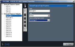
This module allows you to add more GPIO ports to your RM2200D system. This is necessary if your setup needs more GPIOs than there are available on the audio modules. Also, the ports on this module can handle more robust loads then the ones on the audio modules. The module provides:
4 general purpose inputs, insulated with opto-coupler, switchable pull-up resistor.
12 general purpose outputs, insulated, electro-mechanical relays, max. current 1A, max. voltage 30V.
(see also RM220-311 GPIO Module)
Label. Enter a descriptive name for this GPI here. This name will appear in all other parts of the software to identify this input.
Level. Select the option Normal to activate the GPI with a positive voltage. Choose option , if you want the GPI to activate when the input voltage is near zero.
Pull-up. The GPI ports can use a Pull-up resistor . Select option On to use this resistor. You need this if you want to onnect just a switch to this GPI. Choose option to deactivate the resistor.
Label. Enter a descriptive name for this GPO here. This name will appear in all other parts of the software to identify this output.
Type. Select the kind of output the GPO gives when activated. These options are available:
Normal. The GPO carries a positive voltage when activated.
Inverted. The GPO carries a voltage near zero when activated.
Pulse on. The GPO gives a pulse when activated.
Pulse off. The GPO gives a pulse when deactivated.
Output routing logic source. Use this setting to assign an internal logic source to the choosen GPO. Click the button to select any other logic source from the Logic Sources window.
