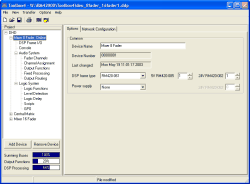
If you select the topmost node of a Device in the project tree, the tabs Options and Network Configuration are displayed in the window on the right. Here you can configure the properties of the selected Device.
This tab contains general information on the Device.
You can configure the following options:
Label: This is the name of the Device that you can change if necessary. If a project contains several Devices, they should be named differently. This makes configuration easier since the Device names are used in different lists. The Label can also be displayed in the main display of the modules RM420-010/011/012/013, though being limited to a length of 16 characters only.
Device Number: The serial number of the Device. It can not be changed.
Last changed: Date and time of the last modification of the Device configuration.
DSP frame type: Here you choose the desired DSP frame, either the frame RM420--061 (3 HE) or the frame RM420-063 (6HE). By selecting the DSP frames, the available number of slots (10 or 30 slots) for configuring the I/O modules is defined. Furthermore, in this row, you can define the number of power supply modules RM420-082 and RM420-085 in the DSP frame.
Power supply: If an additional 3 HE module frame is necessary for power supply. here you can select the RM420-081 and also the number of available 24 V power units carried by this frame. The number of necessary power supply units is taken from a table and released by DHD via the confirmation of order.
![[Note]](../pics/note.gif) | Note |
|---|---|
The options for the power unit are for information only. They have no meaning for the configuration of the Device. | |
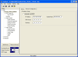
In this tab, you can configure the IP address of the Device. If you check the checkbox Automatic via DHCP, after switching on, the Device tries to receive an IP address from a DHCP server in the network.
If this option is inactive, you can configure a static IP address. Watch the settings in the field Subnet Mask, mostly the value 255.255.255.__0 is set.
If available in the current network, you can also define the addresses of the DNS server and the Gateway. Mostly, both values are set to 0.0.0.0.
(see also Configuration of IP Addresses)
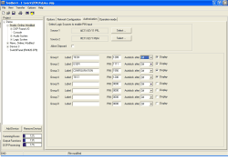
If necessary, you can limit the access to certain functions of the RM4200D using this dialog. This is useful, e.g. if certain settings – like DSP processing, Gain or Equalizer – should be editable only by a limited group of users.
Access restrictions work like this:
The access to certain keys and their assigned functions is restricted. You assign the protected keys when configuring the Console. (see also Authorisation – Restricting Key Access)
You can define up to 8 different user groups. Each group can be assigned a name with a maximum length of 16 digits. You can see this name in the display of the modules RM420-010, RM420-012 and RM420-013.
To log in, first a user has to press two certain keys simultaneously for five seconds. Then, she can enter a four digit PIN using the rotary knob. If the PIN is correct, the user stays “logged in” and has access to the functions that are locked otherwise.
The user retains access to the special functions until she either logs out or a preset timeout has occurred.
To activate access restrictions, you first have to determine which two logic sources allow the entry of a PIN. These two logic sources have to be true simultaneously for five seconds to allow the entry of the PIN using the rotary knob. In addition, they have to stay true until the PIN has been entered completely!
Set the desired logic sources in the lines Source 1 and Source 2. To do this, click on the button respectively and select the logic source from the Logic Sources Window.
![[Important]](../pics/important.gif) | Important |
|---|---|
You can select any logic source available in the Config to enable the PIN input mode. It has proved useful, though, to select two keys that are located on the Console. Select the keys in a way that they can be pressed simultaneously with one hand! You need the other hand for entering the PIN using the rotary knob. | |
![[Warning]](../pics/warning.gif) | Warning |
|---|---|
In any case, make sure to use two “vacant” keys on the Console for this purpose. If you accidentally define a access restricted key for activating the PIN input mode, it will be impossible to use this function. | |
Now define the different user groups. For this purpose, enter the following data:
Label. This is the name of the group, it may be up to 16 digits long.
PIN. Enter the secret number here. It must have four digits and may not have any spaces and no leading 0 (zero). Make sure that each group has an unique PIN!
Autolock after. Here you can define after what time the used is “logged out”. You can set periods of time between 2 and 30 minutes. If you choose the option Off, there will be no time limit. Then the user has to press two keys again for 5 seconds simultaneously to log herself out.
Display. Activate this checkbox if the name of the user group logged in should appear in the display of the modules RM420-010, RM420-012 and RM420-013.
Now, in the pane Console you can define the keys for which access should be limited. (see also Authorisation – Restricting Key Access) As soon as you are done, load the modified Config into the Device. The keys on the Console of the Device are now access protected.
If you want to log in the Console as authorised user, use the following steps:
Press both keys for activating and hold them for five seconds. After this period of time, the input mode becomes active. The display of the modules RM420-010, RM420-012, RM420-013 and RM420-014 switches to PIN 0.
Now turn the rotary knob next to the display left and right until the first digit of the PIN is displayed.
Now turn the rotary knob into the other direction until the second digit is set correctly.
Change direction again and set the third digit, too.
Again, change direction and set the fourth digit of the PIN. If this is correct, the output Success is temporarily shown in the display. After that, the name of the user group is displayed. If you set a time for the autolock function, the remaining time until automatic logout is displayed instead.
Now you have extended access to the Console. Both activation keys do not have to be active any longer.
If an autolock time is set, after this period of time, access is terminated automatically. If there is not autolock time configured, hold the activation keys for five seconds to finish the extended access.
![[Important]](../pics/important.gif) | Important |
|---|---|
Make sure to change the turning direction for each digit when entering the PIN numbers! | |
In this dialog, you can set various options affecting the operation of the Device currently selected.
If the Console of your RM4200D is equipped with motor faders, here you can activate automatic fading when loading setups. This means that open faders crossfade automatically when loading a new setup.
![[Note]](../pics/note.gif) | Note |
|---|---|
Automatic crossfade works only if the Motor Fader Modules RM420-020M or RM420-029M are used on the Console. | |
![[Important]](../pics/important.gif) | Important |
|---|---|
Automatic crossfades do not work if the function Auto Off is activated for one of the faders. (see Fader Channels – Configuring Signal Sources for Faders) | |
Depending on the state of the faders involved, the RM4200D behaves differently. The various cases are listed in the table below:
| Assignment before loading the setup | Assignment after loading the setup | Crossfade | ||
|---|---|---|---|---|
| Fader 1 | Fader 2 | Fader 1 | Fader 2 | |
| Channel 1 Open and On | arbitrary Closed and Off | Channel 2 (from setup) Closed and Off | Channel 1 Open and On | The name of channel 1 is temporarily displayed in both fader displays. Then the crossfade is carried out: Fader 1 is opened, fader 2 is closed. Then fader 2 displays the name of channel 2 that was assigned according to the setup. |
| Channel 1 Open and On | Channel 2 Open and On | Channel 2 | Channel 1 | Both faders remain unchanged. Assignment of channels is not changed. |
| Channel 1 Open and On | Channel 2 Open and On | arbitrary | Channel 1, (According to setup, Channel 2 is not switched to pool fader any more) | Both faders remain unchanged. Assignment of channels is not changed. |
If three motor faders are involved, an automatic crossfade is carried out as well:
| Assignment before loading the setup | Assignment after loading the setup | ||||
|---|---|---|---|---|---|
| Fader 1 | Fader 2 | Fader 3 | Fader 1 | Fader 2 | Fader 3 |
| Channel 1 Open and On | Channel 2 Open and On | arbitrary Closed and Off | arbitrary Closed and Off | Channel 1 Open and On | Channel 2 Open and On |
The crossfade is carried out as follows:
Temporarily, the name of channel 2 is displayed in the fader displays of fader 2 and fader 3. Fader 2 is closed, at the same time, fader 3 moves to the current value of fader 2. The crossfade is carried out in a way that it can not be heard.
In the display of fader 2 (now closed), the name of channel 1 is displayed.
The faders 1 and two are crossfaded. For this, fader 2 moves to the value of fader 1, at the same time fader 1 is closed. The crossfade is carried out in a way that it can not be heard.
![[Note]](../pics/note.gif) | Note |
|---|---|
The function described below is configurable from version 5.5 (Toolbox4 and Firmware). | |
This option activates the storing of fader values in setups. The saved values are stored in dB and accord to the setting of the respective fader potentiometer. This applies to the values of all configured faders.
![[Important]](../pics/important.gif) | Important |
|---|---|
On the loading of a setup containing fader values, the currently set values are overwritten by the saved values without confirmation. Thus, signals might suddenly be mixed onto busses, producing undesirable mixing results.Therefore we urgently recommend using this option during production only. | |
![[Note]](../pics/note.gif) | Note |
|---|---|
The function described below is configurable from version 5.5 (Toolbox4 and Firmware). | |
Before, Routing Selectors (crosspoints) were stored in every setup by default. Consequently, the selection Include Routing Selectors is activated. If you deactivate this function, no future Routing Selectors information will be stored in setups.
![[Note]](../pics/note.gif) | Note |
|---|---|
The function described below is configurable from version 5.5 (Toolbox4 and Firmware). | |
With the aid of the Chipcard ID you can realize fixed assignments of setups stored on chip cards to an RM4200D. This inhibits that an RM4200D will process setup data from chip cards that originate from another, differently configured RM4200D.
By default, the Chipcard ID corresponds to the first 10 characters of the Device name, which you can generate in the menu Options. Modifications of the Device name are adopted for the Chipcard ID until you change the entry in the text field Chipcard ID by hand.
It is also possible to manually enter the same Chipcard ID for several Devices. So you can use the setup stored on a chip card on several consoles. We strongly recommend this procedure only for devices with identical configuration.
The Chipcard ID is stored in the RM4200D. When a setup is backed up, the ID is also copied onto the chip card. If a setup is to be loaded from a chip card, both Chipcard IDs are compared. In case they differ, the setup is not loaded, and the display of the RM420-013 shows Invalid Chipcard instead.
For further information about setups, please see part 6 of the Documentation, Application Software Manual - Setup Manager.
Activate the checkbox Enable Talkback Matrix if you want to operate the selected Device as talkback matrix. Then you can configure the Device as a matrix of x channels and x outputs. The nodes of this matrix can be set by external Devices using the UDP messages. You find an example for this configuration in the volume “Part 2 – System Reference” of this manual.
![[Note]](../pics/note.gif) | Note |
|---|---|
If you activate this option, the selected Device can be used exclusively for talkback and routing functions! Please read the corresponding explanations in the volume “Part 2 – System Reference” in this manual. | |
If you activate the checkbox LL/RR Single Channel mode, you change the operation mode of the functions LL and RR. As soon as you activate these functions on the Console, you only hear the left (LL) or right (RR) channel from the output, respectively the other channel is muted. (see function ON/OFF Function)
The option Preparation mode with fader enables you to switch between the conventional functionality of the conference mode and an especially adjusted version of the conference function.
With the Select key, you first need to select a logic source, which activates the special conference mode. Ideally this should be a toggling key. In the initial state (key not activated), the conference mode works as it is known. For taking part in the conference, the fader potentiometer must be closed, the respective channel has to be switched on (Channel ON), and the key function CF Prep in the fader channel must be activated.
If the Preparation mode with fader option is activated by the assigned key, only those channels take part in the conference, whose CF Prep key function is activated, and which are switched off (Channel OFF). Furthermore, in the conference matrix, you can set the volume of a channel via its fader potentiometer.
There are three bars below the project tree displaying the load of the three main DSP function groups. This display is valid for the Device currently selected in the project tree.
Here, the load of the summing buses is displayed. Each DSP module can calculate up to 16 stereo sums, making up a maximum number of 48 stereo sums available for each Device. The system automatically defines the first stereo sum in each configuration as PFL bus. Further sums are used as Program Buses, Aux Buses and Clean Feeds. If a DSP module is equipped with a RM420-422 Dual MADI Module, twelve routing channels of the TDM bus system are used for the MADI transfer per module. These twelve channels are taken from the total number of channels normally being available for six stereo sums. Thus, the load of the Summing Buses is higher the more MADI modules are used.
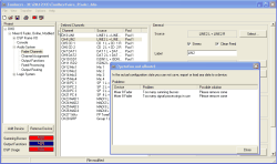
If the calculated load for the configuration is higher than 100%, the color of the bargraph changes from blue to red. If you try to load a configuration in this condition to a Device, the error message Operation not allowed appears:
![[Note]](../pics/note.gif) | Note |
|---|---|
Summation can be used up to a load of 100% without any restrictions. | |
Here, the load of the DSPs with Output Functions and Super Output Functions is displayed. Each DSP module can calculate up to 40 Output Function and 6 Super Output Functions; thus, a RM4200D system can use up to 120 Output Functions and 18 Super Output Functions.
If a DSP module is equipped with a RM420-422S Dual MADI module, 64 routing channels of the TDM bus system are used for MADI transfer per module. 24 channels from the total number of Output Functions and 2 channels from the total number of Super Output Functions are taken, too. Thus, the load display for the Output Functions is higher the more Dual MADI modules are used.
If the calculated load for the configuration is higher than 100%, the color of the bargraph changes from blue to red.
![[Note]](../pics/note.gif) | Note |
|---|---|
Output functions can be used up to a load of 100% without any restrictions. | |
Here, the load of the available DSP Processings for Fader Channel Processing and Fixed Processing is displayed. The display is influenced by the following parameters:
The number of DSP-Processings used.
The number of DSP cycles needed.
The size of the Data Memory used in the DSP.
The size of the Code Memory used in the DSP.
The number of needed routing channels of the TDM bus system.
The display of these values refers to the DSP modules with their actually mounted DSPs used in the Device. Their load is mainly influenced by the number of Fader Modules, since each Fader Module needs appropriate DSP performance for the Fader Channel Processing and the Fixed Processing. Each DSP function used can modify the load.
A DSP module can calculate a maximum of 24 stereo DSP processings, taking up a total number of 72 stereo DSP processings per RM4200D system.
If a DSP module is equipped with a RM420-422 Dual MADI module, 24 routing channels of the TDM bus system are used for the MADI transfer per module. These 24 channels are taken from the total number of channels normally being available for twelve stereo DSP processings. For this reason, the display DSP Processing changes when MADI modules are used.
If the calculated load for the configuration is higher than 100%, the color of the bargraph changes from blue to red.
![[Note]](../pics/note.gif) | Note |
|---|---|
DSP processings can be used up to a load of 100% without any restrictions. Since the display value is calculated from a total of five parameters, the reason for exceeding the maximum load may not be clear. In this case, use the Fitting Report to get detailed information. (see Fitting Report) | |
![[Important]](../pics/important.gif) | Important |
|---|---|
Always make sure all modules have the correct firmware installed and are configured with the appropriate version of the Toolbox4 software. (see Configuration Data) | |


