Table of Contents
Using the Maintenance Window, you have direct access to the hardware components of the RM4200D. This special window works indepentently from the different configuration menus and from the project tree of the Toolbox4 software. It contains special functions that are important for setting up a new system and for maintenance tasks.
![[Tip]](../pics/tip.gif) | Tip |
|---|---|
The Maintenance Window works independently from any project files that might be open. Therefore, there is no need to open a project file if you only want to carry out a firmware update, for example. This is especially helpful for on-site-service if no project file is available. | |
Among others, you can use the Maintenance Window to do the following:
Update the Device tree.
Read out information about connected modules.
Reset individual modules or whole Devices.
Change module IDs when integrating spare parts.
Read out and change the license codes.
Save Mixer Setups.
Monitor the communication on the CAN bus.
To open the Maintenance Window, select the command from the menu. You can also press the key F7.
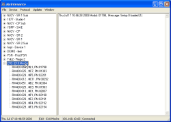
On the left side, the Maintenance Window contains the Device tree with all Devices available. On the right, there is the protocol pane. There, according to the selected settings, you can monitor the communication on the CAN bus.
At the bottom of the window, you find information panes with status displays. You can use many functions using both menu commands and keyboard short cuts. Besides, you can bring up the context menu in several places by pressing the right mouse button.
The Device tree displays all RM4200D Devices accessible to the software. This list is generated automatically by UDP messages. However, if building the list does not work correctly, you can manually add missing Devices. This is useful, if the existing network does not transfer UDP packets properly across different network segments or through firewalls. (see Add device... (Setting up a connection to RM4200D manually))
In the tree view, you can select the individual Devices and their modules that you want to work on. In the Device tree, the Project ID consisting of up to 4 characters is displayed on the left and the first ten characters of the Device Name are shown in the middle. On the right, the serial number of the Device is shown. This number consists of the DHD-specific bytes from the Ethernet address of the Device. The tree view lists all Devices in alphabetical order.
In contrast to the project tree in the configuration window, the Devices in the Device tree are not displayed according to a hierarchy! All available Devices are displayed vertically, although they might be parts of different projects. For each active Device, you can open another branch by clicking on the plus symbol in front of the Project ID. For the given Device, this branch displays all modules that are connected to the CAN bus and ready for operation. It does not matter whether this module is available in the current Config or not!
You can also display detailed information about the modules contained in the different backplanes of a DSP frame: Click on the plus sign in front of the DSP Controller module RM420-851. The display will expand to another subsection. In this section, all operational I/O modules contained in the backplane are listed. For each module its slot number, type and serial number are displayed.
Except for the DSP Controller module RM420-85, none of the listed modules is connected to the CAN bus. Again, it does not matter if the modules are contained within the current Config or not!
![[Warning]](../pics/warning.gif) | Warning |
|---|---|
For all RM4200D Devices displayed in the Device tree, certain commands (e.g. F12 = Reset) can be triggered without confirmation. Especially in networks with more than one RM4200D, make sure to select the correct system! | |
