With this command you can manually set up the connection to a RM4200D, if it is connected via the serial port or if the automatic registration using UDP does not work.
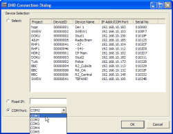
After using the command , the DHD Connection Dialog opens. Now you have the following options to set up a connection to a Device:
Select. In the upper part of the dialog, all Devices within the same network segment as the PC running the Toolbox4 software are listed. This list is automatically build from UDP messages received from the DSP frames on the network. For each Device the following information is displayed: its project ID, its name and its serial number. This number is identical to the DHD-specific bytes of the Ethernet MAC address of the Device. Select the desired Device by clicking on its entry.
Fixed IP Address. Here you can enter the IP address of a Device manually. You may need to do this, if no UDP packets are received by the Toolbox4-PC, causing the Device list to be incomplete. You can also use this option if you need to remote access RM4200D systems over wide area connections.
![[Important]](../pics/important.gif)
Important If the Device is assigned its IP address via DHCP, the address can change depending on the settings. In this case, you have to find out the address currently assigned in a different way, e.g. by a state request to the DHCP server. Therefore, it is easier to work with static IP addresses only. (see also Configuration of IP Addresses)
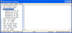
COM Port. Select the serial port the Device is connected to. Make sure the port is not already used by other applications or a Toolbox4 software running at the same time! If you close the dialog using the button OK afterwards, the Device is displayed at the selected port in the Device tree. A Device currently connected and switched on is marked by a „+“ in front of the entry COM1 (2...4, respectively). The node can be opened by clicking on it, the branch displays all modules connected to the CAN bus of the Device and ready for operation. (see figure 14: Modules in the Device tree, the Device is connected via the serial port COM 1. )
This command updates the information of all Devices displayed in the Device tree. The list of Devices is sorted alphabetically.
With this command, you can display the current state of a module. To do this, select the desired module – you may have to click on the node in front of the desired Device first to display all available modules.
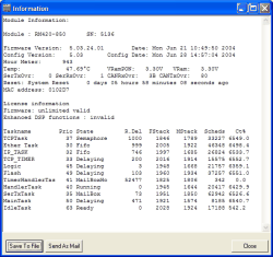
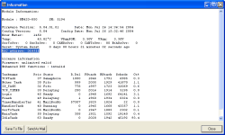
Now use the command , the key F11 or the contextual menu to open the window Information. This window displays all available information as text. To save it to an ASCII file, click the button . If the PC is set up accordingly, you can also e-mail this text to DHD. Click the button to do so.
![[Important]](../pics/important.gif) | Important |
|---|---|
The displayed files are read out from the selected module and displayed, when the command is selected. The display is not updated automatically afterwards! Please note also that the displayed values for voltage, temperature and frequency are not as exact as the number of displayed characters might suggest. | |
The content of the status window can vary depending on the kind of module (see the column Remarks in the following table) and is divided into two panes:
General information and information on hardware (top).
Information on software and operating system (bottom).
The following table contains example values and the corresponding explanations:
This information gives an overview of the processes running on the real time operating system of the microcontroller. All values are up to date at the moment you are selecting the command . This information is interesting for an advanced diagnosis of the system by a software developer. To avoid overflows in the display of the parameters Scheds and Ct%, you have to access the display in time periods of less than 34 minutes. This means normally that you should access the display twice shortly after another – the last display is then free of overflows.
The following table shows typical example values for the diagnosis data:
| Remark | Taskname | Prio | State | R.Del | FStack | MStack | Scheds | Ct% |
|---|---|---|---|---|---|---|---|---|
| all modules | Flash | 49 | Delaying | 90 | 1960 | 1934 | 5 | 0 |
| all modules | TimerHandlerTas | 41 | MailBoxHo | 28945 | 1825 | 1824 | 5 | 0 |
| all modules | HandlerTask | 40 | Running | 0 | 1945 | 1707 | 77 | 1.4 |
| all modules | SerTxTask | 35 | MailBoxHo | 0 | 1947 | 1863 | 26 | 0 |
| all modules | MainTask | 50 | Delaying | 71 | 1914 | 1732 | 8 | 0 |
| all modules | IdleTask | 63 | Ready | 0 | 2028 | 1934 | 77 | 7.2 |
| RM420-850 | TCPTask | 37 | Semaphore | 1000 | 1846 | 1789 | 5 | 0 |
| RM420-850 | Ether Task | 30 | Fifo | 0 | 2006 | 1928 | 5 | 2.9 |
| RM420-850 | IP_TASK | 32 | Fifo | 264 | 1997 | 1690 | 74 | 3.4 |
| RM420-850 | TCP_TIMER | 33 | Delaying | 200 | 2016 | 1950 | 33 | 0 |
| RM420-850 | Logic | 45 | Delaying | 9 | 1927 | 1690 | 9 | 46.5 |
| RM420-851 | DSP | 45 | Delaying | 6 | 1784 | 1605 | 8 | 25.4 |
| RM420-010 | MainModule | 45 | Delaying | 1 | 1949 | 1670 | 8 | 10.6 |
| RM420-011 | StudioUnit | 45 | Delaying | 14 | 1950 | 1715 | 8 | 8.6 |
| RM420-012 | Central | 45 | Ready | 0 | 1940 | 1671 | 9 | 9.7 |
| RM420-013 | Overbridge24 | 45 | Delaying | 3 | 1950 | 1663 | 5 | 2.7 |
| RM420-020 | Fader | 45 | Delaying | 8 | 1927 | 1657 | 93 | 5.3 |
| RM420-025 | Overbridge40 | 45 | Delaying | 8 | 1951 | 1793 | 28 | 5.9 |
| RM420-026 | Overbridge32 | 45 | Delaying | 10 | 1951 | 1778 | 14 | 5.2 |
| RM420-029 | Fader029 | 45 | Ready | 0 | 1902 | 1651 | 29 | 9.9 |
This command displays the current data of all modules of a Device that are connected to the CAN bus and ready for operation. You have to select a Device in the Device tree first to be able to use this command. A new window Module information opens afterwards. The information about the individual modules are separated from each other by stating the Type of module, the module ID and by hyphens. The content corresponds to the information described in the previous section.To save the output text to an ASCII file, click the button . If the PC is set up accordingly, you can also e-mail it to DHD. Click the button to do so.
With this command you can restart the selected Device. It does not matter whether a module of the Device is selected in the Device tree or the name of the Device itself. Alternatively, you can also reset the Device by pressing the F12 key.
In addition, you can reset a whole Device or individual modules by highlighting the desired entries in the Device tree and using the contextual menu.
![[Warning]](../pics/warning.gif) | Warning |
|---|---|
The reset is carried out immediately without any confirmation. Make sure to select the correct Device or module! | |
![[Important]](../pics/important.gif) | Important |
|---|---|
After a Reset, the setup saved using the command is loaded, not the condition before the reset that is saved in the parameter RAM! The data saved there is only loaded after switching off/on, if the value VRamPON of the support voltage was higher than 2.0 V when switching on. | |
With this command, you copy the current content of the parameter RAM of a Device to storage space Setup 0 in the Flash memory of RM420-850. This way, the settings are kept after switching off the Device and can be used as Default Setup for a reset. In addition, Setup 0 can be loaded like all other setups using the Console.
![[Note]](../pics/note.gif) | Note |
|---|---|
You can save Setup 0 using this command only! This is not possible using the Console! | |
First you have to select the desired Device to trigger the command. Afterwards, a confirmation dialog appears, saying Save current Parameter settings?. When confirming with “Yes”, the settings are copied. In addition, on the right in the protocol pane the execution of the command is acknowledged by the module RM420-850:
2004-06-28 17:57:40.423 RCV TCP Stud2 Module 5194 Code 0310: Message: Setup 0 saved in RAM
2004-06-28 17:57:41.641 RCV TCP Stud2 Module 5194 Code 0312: Message: Setup stored in Flash
The plain text display of these messages is stored in the file “err.err” that has to be available on the PC. If this is not the case, the messages are displayed with their identification numbers:
2004-06-28 17:58:11.438 RCV TCP Stud2 Module 5194 Code 0310: Parameter1 0 Parameter2 0
2004-06-28 17:58:12.982 RCV TCP Stud2 Module 5194 Code 0312: Parameter1 0 Parameter2 0
![[Important]](../pics/important.gif) | Important |
|---|---|
It is important to use the command immediately after each initial setup or change of configuration of the faderchannels of a RM4200D! This is the only way how the system can start with reasonable parameters after a reset, especially for Analog Gain, Phantom voltage, Fader assignment and Bus switching! | |
As with the command you can use this command to copy the content of the parameter RAM to the storage spaces Setup 1 to Setup 6 in the Flash memory of the RM420-850. You can pre-load the Setups 1 to 6 with reasonable values. The user of the RM4200 can activate the setups at the Console.
In contrast to Default Setup 0, the setups 1 to 6 can also be saved at the Console. Therefore, use the key function Save Mixer Setup in cooperation with rotary selectors. (see function Load/Save Functions)
![[Tip]](../pics/tip.gif) | Tip |
|---|---|
When you saved the Default Setup 0 during configuration of a RM4200D, it may be useful to save the same setup also on the spaces Setup 1 to Setup 6. In operation, you can then load this basic setup at the Console, modify it as needed and then save it back to the desired storage space. | |
To use the command, you first have to select the desired Device. A confirmation dialog appears. When you confirm this dialog, the data is copied and the execution of the command is acknowledged in the protocol pane:
2004-06-28 16:59:36.306 RCV TCP Stud1 Module 2224 Code 0310: Message: Setup 1 saved in RAM
2004-06-28 16:59:37.425 RCV TCP Stud1 Module 2224 Code 0310: Message: Setup 2 saved in RAM
2004-06-28 16:59:37.747 RCV TCP Stud1 Module 2224 Code 0312: Message: Setup stored in Flash
2004-06-28 16:59:38.545 RCV TCP Stud1 Module 2224 Code 0310: Message: Setup 3 saved in RAM
2004-06-28 16:59:39.686 RCV TCP Stud1 Module 2224 Code 0310: Message: Setup 4 saved in RAM
2004-06-28 16:59:40.106 RCV TCP Stud1 Module 2224 Code 0312: Message: Setup stored in Flash
2004-06-28 16:59:40.806 RCV TCP Stud1 Module 2224 Code 0310: Message: Setup 5 saved in RAM
2004-06-28 16:59:41.925 RCV TCP Stud1 Module 2224 Code 0310: Message: Setup 6 saved in RAM
2004-06-28 16:59:42.271 RCV TCP Stud1 Module 2224 Code 0312: Message: Setup stored in Flash
Two setups are saved in one segment of the Flash EPROM, therefore the message Setup stored in Flash is displayed only three times.
If the file “err.err” with the plain text messages does not exist, the identification numbers of the messages are displayed:
2004-06-28 17:06:15.618 RCV TCP Stud1 Module 2224 Code 0310: Parameter1 1 Parameter2 0
2004-06-28 17:06:17.024 RCV TCP Stud1 Module 2224 Code 0310: Parameter1 2 Parameter2 0
2004-06-28 17:06:17.135 RCV TCP Stud1 Module 2224 Code 0312: Parameter1 0 Parameter2 0
2004-06-28 17:06:17.876 RCV TCP Stud1 Module 2224 Code 0310: Parameter1 3 Parameter2 0
2004-06-28 17:06:19.342 RCV TCP Stud1 Module 2224 Code 0310: Parameter1 4 Parameter2 0
2004-06-28 17:06:19.348 RCV TCP Stud1 Module 2224 Code 0312: Parameter1 0 Parameter2 0
2004-06-28 17:06:20.117 RCV TCP Stud1 Module 2224 Code 0310: Parameter1 5 Parameter2 0
2004-06-28 17:06:21.239 RCV TCP Stud1 Module 2224 Code 0310: Parameter1 6 Parameter2 0
2004-06-28 17:06:21.658 RCV TCP Stud1 Module 2224 Code 0312: Parameter1 0 Parameter2 0
With this command, you reset the content of the parameter RAM to its default values, as follows:
All Gain settings are reset to 0 dB.
All analog Gain settings are reset to 0 dB.
All AUX buses are reset to Post Fader.
All inputs (Fader Channel) are switched onto the buses.
All EQ frequencies are set to 1000 Hz.
Phantom voltages are switched off.
![[Tip]](../pics/tip.gif) | Tip |
|---|---|
If you want to delete mixer Setups, do the following:
You have now deleted all custom setups and written default values to their storage space. | |
![[Note]](../pics/note.gif) | Note |
|---|---|
If you have to manage several RM4200D systems you may find yourself handling setups frequently. In this case, you should use the Setup Manager software. This application comes free with every RM4200D on CD. | |
With this command, you can enter the license codes that are vital for the function of the software of the RM4200D. There are license codes for the operation of the software itself and additional codes for enabling the Enhanced DSP Functions. The latter enable optional processing functions and must be ordered separately. (see Fixed Processing – Defining Fixed DSP Functions)
![[Note]](../pics/note.gif) | Note |
|---|---|
An invalid license code allows the operation without restrictions (except Enhanced DSP Processing) of the RM4200D for a duration of 600 hours, which corresponds to 25 days non-stop operation. After that, a "License invalid" message appears in the Rotary Encoder Displays of the Control Modules (RM420-010, RM420-012, RM420-013, …). Except this message and the Enhanced DSP Processing, operating the system is still possible without restrictions. After 800 hours of operation without a valid license, the system causes a reset about once per hour. The Enhanced DSP functions are inactive when an inactive license code is used, signals are only bypassed in the DSP (bypass mode). | |
In general, a valid license code that is saved in the Communication&Logic Controller RM420-850 is necessary for operating the RM4200D. Each module RM420-850 has its own license code which is based on the last three bytes of the Ethernet MAC address of the module.
There are two ways to find out the Ethernet MAC address:
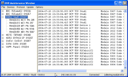
First, it is always shown in the project tree of the Maintenance Window. You will find it as the six-digit code to the right of the project ID and the name of the Device.
Second, the MAC address is also listed in the information window of a module. Just select the desired module in the project tree and choose the command from the menu . You can also use the function key F11. You will find the MAC address in the line labelled MAC address on top of the information window.
![[Important]](../pics/important.gif) | Important |
|---|---|
If you exchange a module RM420-850, you may need a new license code that you can order from DHD. When ordering, please name the last three bytes of the Ethernet MAC address. You can have displayed the address of the module using the command (functional key F11), the value is displayed in the line MAC address (e.g. 01:00:ce). | |
In most cases, RM4200D systems are shipped by DHD with a time limited license code (marked valid until...). As soon as the system has fully passed into the property of the customer, DHD sends an e-mail with a permanent license code.When you received a license code, you should first copy it into the clipboard using the key combination Ctrl+C. Now select the desired Device in the Device tree and select the menu command . Then copy the code from the clipboard into the input field using the key combination Ctrl+V and confirm by clicking . The code is transferred into the Device. Check the reception of the code for the module RM420-850 by using the command . If this is the case, the output for License information is now unlimited valid or valid until with a new date for time-limited license codes respectively.
A wrongly entered license code is ignored!
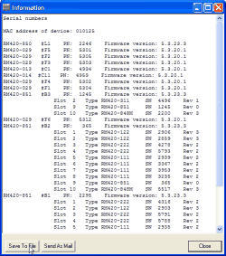
With this command, you can output all serial numbers of the modules of a Device connected to a CAN bus including the audio I/O modules and the DSP modules. The numbers are displayed in the protocol pane of the Maintenance Window, additionally, also the software versions active on the separate modules are displayed. To save the output text to an ASCII file, click the button . If the PC is set up accordingly, you can also e-mail it to DHD. Click the button to do so.This command is for information only.
