Table of Contents
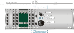
- 7.1. RM220-061 DSP Frame 3U/19“
- 7.2. RM220-111 Digital In/Out/GPIO module, 8 channels
- 7.3. RM220-122 Mic/Headphone/GPIO Module, 4 channels
- 7.4. RM220-222 Analog In/Out/GPIO Module, 4 channels
- 7.5. RM220-223 Analog In/Out/GPIO Module, 4 channels
- 7.6. RM220-228 Analog In Selector Module (stereo)
- 7.7. RM220-311 GPIO Module
- 7.8. RM220-951 DSP, MADI & Communication Controller
- 7.9. Color Codes for Network Cables
This chapter contains all the reference information you need to install and operate the RM2200D.
![[Warning]](../pics/warning.gif) | Warning |
|---|---|
Please make sure you understand all information in this chapter before installing the RM2200D. Failing to do so can cause damage both to the RM2200D and any other equipment connected to it! | |
