With this command you can activate the password protection for certain parts of the software. Usually, the settings for the used inputs and outputs (command I/O Setup) and for the pre-settings of the software itself (command Preferences) are protected by a password.
![[Important]](../pics/important.gif) | Important |
|---|---|
When first starting the Routing Software, the pre-set password is “default”. | |
When you start the program Route.exe and try to use one of these commands, you have to enter the right password. Once you did so, access to the two commands is activated for 15 minutes. Afterwards you have to enter the password again. However, for re-activating the password protection before these 15 minutes are over, please use the command Lock Setup. A dialogue is displayed for confirmation, and afterwards, the password protection is active again.
![[Tip]](../pics/tip.gif) | Tip |
|---|---|
For entering or changing the password, please select the command Preferences from the menu Setup. Click on the register tab Security and then on the Set… button. Now you can enter the new password. After re-confirming it in another dialogue, the password is changed. | |
This command opens a dialogue, with the aid of which you can define, to which input and output signals the Routing Software is to have access. These settings are very important for the operation of the program, thus they are protected by a password. Please read later on in this manual how to change the password. (see also Security)
![[Note]](../pics/note.gif) | Note |
|---|---|
Depending on the size, RM4200D-Routers can have very many inputs and outputs, which are not necessarily used. In such cases, you can control the Routing Software better, if only those inputs and outputs are displayed, which are actually used. | |
You can activate this command also by clicking on the following icon in the main screen:

Before you can configure the signals, you first have to select from which source the data for the configuration of the router should come from: You can either load them from an existing project file (*.ddp), or transfer them directly from an RM4200D system in the network. By downloading, the Routing Software will receive the information necessary for the configuration, for instance about the available audio sources on the TDM bus, about configured outputs, the project ID and Device names.
| Note |
|---|---|
It does not matter if you load the configuration from a project file or directly from an RM4200D router. The stored information is equal. | |
Before you can actually start configuring inputs and outputs, a dialogue is displayed, in which you can select the data source. It is there where you have to decide if the information is to be loaded from a project file or from a Device.
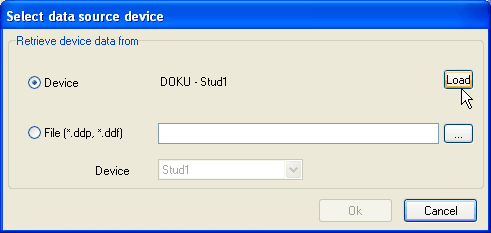
In order to load the data from a configuration file, please activate the radio button File (*.ddp, *.ddf). Then click on the button; a file dialogue is displayed. Select the desired project file. Afterwards all Devices from the project file are displayed in the pop-up menu Device. Select the Device that you want to remote-control with the Routing Software.
If the Routing Software already has been connected to a Device, and if this Device also is available in the network, it is displayed with project ID and Device name behind the radio button . If you hit the button, the current configuration is downloaded from the Device into the Routing Software.
If software has not yet been connected to a Device, or if this Device is not available in the network, you cannot use the Device option. In this case, Not connected is displayed.
Click the OK button after selecting the data source. Now the dialogue opens, in which you can configure the inputs and outputs:
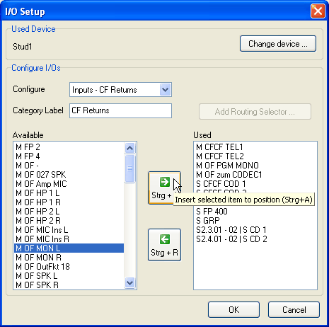
In the upper area Used Device you can see, which Device you are currently configuring. If you want to access another Device, click the button. The just described dialogue for selecting the data source opens and you can select a different Device.
The Configure I/Os area of the dialogue serves for assigning the inputs and outputs that are “visible” to the Routing Software.
| Tip |
|---|---|
With respect to the Routing Software, it does not matter, which or how many of the signals available you are viewing. However, it is helpful only to configure those signals, which are actually used. Thus the screen display of the program becomes more clearly laid out, and the probability of faulty mal-operations decreases. | |

The Configure I/Os area contains the following elements:
Configure: Please select with this pop-up menu if you want to configure the inputs or the outputs of the router. There is one entry for the outputs (Outputs); however, there are five different categories for the inputs (Input - <Category Name>). Please select here, which signal group you would like to work with.
Tip You can subdivide the inputs available into five categories. Each input can be located in exactly one category. As desired, you can then show or blank these categories in the display of the router status.
Category Label: In this input field you can assign a name for the currently processed category of input signals. If you are just working on the output signals, you cannot use this field.
Add Routing Selector: This button is only available when you are configuring outputs. On clicking it, another dialogue appears, in which you can insert and name a new Routingselector. This Routingselector then appears in the display as additional output. For more explanations please read the next section.
Available: The left list contains all the signals available that have not been assigned yet.
Used: The right list contains all signals that you already have selected for the display. You can change the order of the signals in the display by moving the entries within the list with Drag&Drop. The order of the entries in the list indicates how the signals are arranged in the matrix view - left to right for outputs and top to bottom for inputs.
The display of the available audio sources and outputs concisely contains the following information:
| Category | Label | Explanation |
|---|---|---|
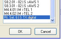
| Output | S8.1.01 - 02 │ S>CD R | Stereo output (S) Slot 8. Port 1. Output 01 and 02 │ Label |
| Output | M4.4.01 │ M>TEL | Mono output (M) Slot 4. Port 4. Output 01 │ Label |
| Output | Rt. Sel. 6 │ S TX digital | Routingselector (Rt. Sel.) Number │ Label |
| Source | M OF PFL Spk | Mono (M) Output Function Label |
| Source | S12.1.01 - 02 │ CD | Stereo input (S) Slot 12. Port1. input 01 and 02 │ Label |
| Soruce | S PGM BUS 1 | Stereo bus (S) Label |
Instructions for the configuration of signal inputs:
First, please select the category of inputs that you want to process in the pop-up menu Configure.
If you like, you can now label the selected category in the Category Label field. This name will then be respectively displayed in either the matrix view or the list view of the main window.
Now, in the left list, click on an input that you want to assign to the selected category. Hit the upper of the two buttons in the centre between the lists or use the shortcut Strg+A for moving the selected input from left list to right list.
Select another output in the left list and proceed the same way. Repeat this procedure until you have assigned all desired signals.
If you want to delete an entry from the right list, select it by clicking and use the lower of the two buttons in order to move the entry back to the left list. Or use the shortcut STRG+R.
| Note |
|---|---|
Each Signal can be located in only one of the two lists. If you move it from one to another, it will disappear from its original place. So duplication of crosspoints is avoided in the router matrix. | |
Configuration of signal outputs:
Please select the entry Outputs in the Popup-Menu Configure.
Click on the desired entry in the left list. Use the upper button between the lists or the shortcut Strg+A to assign the entry to the list on the right side / to the right list.
Proceed the same way with all other output signals that you want to make “visible” for the software.
If you want to delete an entry from the right list, select it by clicking and use the lower of the two buttons in order to move the entry back to the left list. Or use the shortcut STRG+R.
If you like, you can, in addition to the existing RM4200D outputs, define routing selectors as a kind “virtual outputs”. Defined routing selectors appear in the matrix and list views just like normal outputs.
| Note |
|---|---|
Routing selectors are used to, within the RM4200D, route signals to the TDM bus, where they are available for further signal processing. This is the crucial difference to a direct routing to outputs - there, input and output signals are directly connected. In the Routing Software, routing selectors are then used when an RM4200D router is not only to be operated by the software, but in parallel additionally via routing pushbutton panels in control desks or in router control panels with LCD keys. In these cases, you have to realize the routing via routing selectors, as this is the only way that all control elements involved can synchronously display the actual router state. For more details, please see in Part 3 of this manual, “Toolbox 4 Configuration Reference”. | |
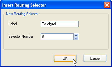
If you want to create a routing selector, click on the Add Routing Selector… button. An extra dialogue opens. In the field Label you can name the routing selector, in the field Selector Number you can select, which routing selector is to be used. You can use each selector only once, however, you have overall 768 routing selectors at your disposal. If you want to assign an already assigned routing selector, the dialogue shows the message This Selector Number is already in use! In this case you have to select a number that has not been assigned yet.Now hit the button in order to define the routing selector. The dialogue disappears, and the re-defined routing selector appears in the right list with the output signals in use.
If you want to delete an already defined routing selector from the list, select it by clicking and then use the upper of the two buttons between the lists. You can also use the shortcut STRG+R. the routing selector is deleted from the list; in order to restore it, you will have to re-define it.
| Important |
|---|---|
It is crucial that the defined routing selectors are used accordingly in the Config of the RM4200D router - i.e. for instance that they are linked with output functions or Super output functions or directly connected with outputs in the output routing. If this is not the case, signal assignments to routing selectors remain ineffective, because the signal is not continued in the RM4200D! (Please read more about this in Part 3 of the manual, “Toolbox 4 Configuration Reference”). | |
Normally, the Routing Software uses the names that have been assigned in the Config of the RM4200D Router for all signals. However, occasionally it is practical to change the names to simplify the operation of the software. Depending on the operation in each respective application, you can use the Rename I/Os command to adapt the signal names.
| Tip |
|---|---|
The names for the signals (OF, CF, FP, SOF, etc.), which are stored in the Config, often are not explanatory enough or even confusing for the actual Routing Software user. For these cases you can change the desired names in accordance with the user. | |
| Note |
|---|---|
If you change signal names, these changes are only stored for the individual copy of the Routing Software that you are modifying. This “renaming” is not stored in the RM4200D. The name assignment is stored in the file io.cfg.This file is located in the same directory as the program file of the Routing Software; it contains all settings of the program. | |
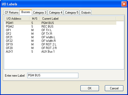
If you call the command Rename I/Os, a dialogue with six register tabs appears. Five of the cards contain the input signals of the five assigned categories, the sixth cards contains the defined outputs. (See also “Configuration of Inputs and Outputs” on page 51.)
The column I/O Address contains the internal name of the signal, the way it is stored in the Config of the Device. The column M/S shows if the signal is available as Mono ("M") or Stereo ("S"). The column Current Label displays the current name of the signal, the way it is used within the Routing Software.
In order to change the name of the signal, please first click on the tab for the category in which the signal is located. The list with the signals of this category is displayed. Click on the signal that you want to change. Now you can enter the new name in the input field Enter new Label. The name will change accordingly in the list while you are typing. Having finished writing, hit the button. The button cancels all changes.
With this command you access the dialogue, in which you can assign the pre-settings for the Routing Software. The dialogue consists of several areas, which are arranged as register tabs. Click on the respective tab for activating the desired area.
| Note |
|---|---|
The dialogue for the pre-settings is, just as the command I/O Setup, protected with a password. If you have not used any of these commands yet, you have to enter the password in order to access the pre-settings. Afterwards you can access it without password for 15 minutes. Within this time, you can activate the access protection with the command Lock setup in the Setup menu.You can change the password in the area Security of the pre-settings dialogue. (see Security) | |
In this dialogue, you can define, with which RM4200D the RoutingSoftware is to be connected.
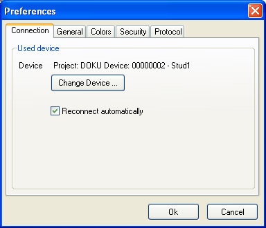
Behind the word Device you can see which Device is currently connected to the software. For this Device, Project ID, Device ID and Device name are displayed. If no device is connected, the word none is displayed.
If you want to connect a different Device, click the Change Device… button. The DHD Connection Dialogue opens and you can establish the connection to another device. Please see Part 3 of this manual, “Toolbox 4 Configuration Reference” for more information about the DHD Connection Dialogue.
I you want the Routing Software to automatically re-install the connection to the Device after a separation, mark the Reconnect automatically checkbox.
In this dialogue you can define general settings for software operation.
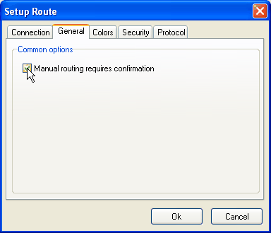
Presently, this dialogue only contains the item Manual routing requiresconfirmation. If you activate this checkbox, the software will always perform an authentication mechanism, when you manually set a crosspoint.
In this dialogue you can set the colours that the software will use for showing the different operation states of the matrix. For this, you can use the 16-bit system colours and the colours of the active Windows XP palette.
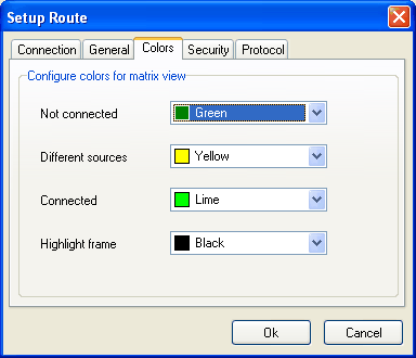
You can separately set the colours for the following states:
Not connected. The crosspoint is not.
Different sources. You can connect two different input mono signals to a stereo output. In this case, the left channel and the right channel contain two different signals. You can select here, in which colour this state will be shown in the matrix view.
Connected. The crosspoint is active, inputs and outputs are connected to each other.
Highlight frame. This colour marks the currently selected crosspoint.
In this dialogue, you can define the password for limiting access to the commands I/O Setup and Preferences in the Setup menu. In order to activate this protection you need to mark the Changing configuration requires Password checkbox.
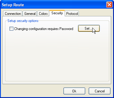
If the access protection is activated, you need to enter the correct password before you can use the commands I/O Setup or Preferences. Afterwards access is activated for 15 minutes. You can terminate access within this time if you call the command Lock setup from the Setup menu.For changing the password, hit the Set… button. An input field is displayed, in which you can enter the new password. Please confirm with the enter key or with the OK button. The same dialogue is shown again; please enter the new password here in exactly the same way for confirmation. Only if both confirmations are identical, the password is changed. Otherwise the software will show en error message. An error message will also be displayed if you leave the input fields blank.
| Note |
|---|---|
The password can have any number of characters (case sensitive); special and space characters are treated like all other characters. If you use the keyboard layout in different languages, you should not use umlauts and other language-specific letters in the password. Thus you will avoid problems when entering passwords with a different keyboard layout. | |
| Important |
|---|---|
The default password is "default". Please use it if you have not defined your own password yet. | |
| Note |
|---|---|
In newer versions of the Routing Software, the protocoling of processes is completely managed by the DHD Communication Server. Therefore, newer versions of the Routing software do no longer contain this register tab. More information about the DHD Communication Server can be found in this manual.In this dialogue you can set how the Routing Software is to protocol all processes. Every time when a crosspoint is set, the software is creating an according entry in the protocol file. It protocols time and which input signal was connected to which output signal.All entries are realized by default in the Route.log,file, which is located in the same directory as the software program file. Initially, the maximum size of the file is not limited. The entries are written on exit of the Routing Software.You can control with the following radio buttons, how the protocol files are written:
Unlimited. A protocol file is written; its size is not limited.
One file per Day. Every day a new file is created. The file name is extended by the date (RouteYYYY-MM-DD.log)If you additionally activate the Delete after checkbox, you can select, after which number of days (1-100) older protocol files shall be deleted.
Max. file size. With this option, the protocol file is updated until it reaches a maximal size. After this, the oldest entries are deleted in the file in order to create space for new entries.