During a Routing Software Session, you will normally use the applications main dialogue, which displays the current state of the router. Simultaneously, you use this view, to set or release crosspoints.
The state of the router can be displayed in two possible views: In the matrix view, input signals and outputs are arranged in a two-dimensional matrix; states of crosspoints will be shown in different colours. In the list view, input signals and outputs are listed in columns. If required, you can switch on or off groups of signals.
It makes no difference which view is used to control crosspoints; you may switch any time between both modes via the View menu.
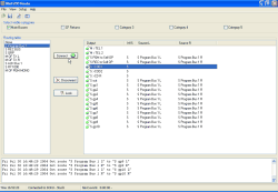
The list view is displayed by clicking the command Routing Table from the menu View.
The list on the left hand side contains the available input signals. All sources are listed with the names set in the configuration by the Toolbox4 software. Stereo sources are indicated by an “S” in front of their name, “M” indicates mono signals. On the very top of the list, you can find source “None”, which can be used to mute an output.
The larger list on the right hand side contains all available outputs. As well as for input signals, all outputs are listed with the names set in the configuration by the Toolbox4 Software. Stereo outputs are indicated by an “S” behind their name, “M” indicates mono outputs. Signals, which are connected to an output, are displayed in the L and R columns. If you assign “None” to an outout, it will be muted; the columns L and R will then be empty.
![[Tip]](../pics/tip.gif) | Tip |
|---|---|
Use the checkboxes in the Select visible categories area to display or not groups of signals. , um bestimmte Gruppen von Signalen ein- oder auszublenden. The corresponding assignment can be set in the dialogue I/O Setup. (see also I/O Setup -Assigning Inputs and Outputs) | |
![[Important]](../pics/important.gif) | Important |
|---|---|
You are able route one audio source to several outputs at the same time. Inversely, it is not possible, to connect several sources mixed to one single output. | |
To connect an input source to an output, follow these steps:
In the left hand list, click on the desired input signal. It sill be selected.
In the right hand list, click on the output, which you would like to connect with the input signal. Between both lists, one or two buttons labelled Connect will be displayed now.
 Figure 37: Buttons to set crosspoints: The left button is for similar signals (both mono or stereo), the pair of buttons is for separate connection of left and right channel.
![[Note]](../pics/note.gif)
Note If input signal and output are of the same type - both signals are either mono or stereo - a single buttons appears, labelled Connect. If you have chosen a stereo input signal and you would like to connect it to a mono output, only the left channel of the input will be connected to the output.
If you would to connect a mono input signal with a stereo output instead, two Connect buttons will appear. Depending on which of the buttons you click on, a corresponding connection will be established. Alternatively, you can also assign a mono signal to the left or the right or even both output channels.
Click the Connect button to establish the desired connection. If you did no changes in the preferences of the software, you have to confirm a security alert, before the switching operation is executed. If you like, you can disable the security request. (see General)
If you like to unlink an active connection, select the relevant output in the list and click on button Disconnect. If you did no changes in the preferences of the software, you have to confirm a security alert, before the connection is released. After confirmation, source None is being routed to the selected output. The output is without any signal.
You can also protect crosspoints from unaware release or changing. Choose the output, you would like to protect and click button . Now, a red U-lock icon is displayed in front of the list entry, indicating that the output cannot be changed anymore until it is released again.
Inversely, you can suspend cover by selecting the protected output from the right hand list and clicking on button Unlock. In the first column of the list, an opened green U-lock is displayed. The crosspoints can be changed again from now on.
![[Note]](../pics/note.gif) | Note |
|---|---|
Please see, that you first select an output, before locking or unlocking a crosspoint. Otherwise, the buttons will be inactive! | |

![[Important]](../pics/important.gif) | Important |
|---|---|
Locking and unlocking of crosspoints does only work within one single copy of the Routing Software. A protection of a crosspoint is not being communicated from one PC to another, which takes control of the same RM4200D router. Locking of crosspoints is realised inside the Routing Software and not in the RM4200D router hardware. | |
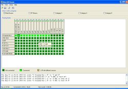
With the Routing Matrix command from the menu, you enable the displaying of the state of the router as a matrix of inputs and outputs.
All inputs are arranged on the left hand side of the matrix from top to bottom and all outputs are placed from left to right at the top edge. Crosspoints are displayed as coloured quadrangles at the interconnetions of inputs and outputs. You can doubleclick on one of these crosspoints to close or open a link. If you did no changes in the preferences, you need to confirm an alert before the switching is done. It is possible to deactivate these security notifications in the preferences menu. (see General)
![[Important]](../pics/important.gif) | Important |
|---|---|
You are able to route one audio source to several outputs at the same time. Inversely, it is not possible, to connect several sources mixed to one single output. | |
![[Tip]](../pics/tip.gif) | Tip |
|---|---|
If you leave the mouse cursor above a specified crosspoint for a second, a tooltip will appear. It will display which signals are connected by that crosspoint. The information is formatted input signal -> output. It is completed by the note Double click to switch. | |
In the matrix view, states of crosspoints are indicated by different colours. By default, opened crosspoints are indicated in dark green, activated crosspoints in light green. If both channels of an output are linked with two different input signals, this crosspoints will be shown in yellow. The caption below the matrix view shows the meaning of the used colours. If you like, you can change the colours in the dialogue, tab . (see Colors)
![[Tip]](../pics/tip.gif) | Tip |
|---|---|
Use the checkboxes in the Select visible categories area, to switch on or off specified groups of signals. A corresponding group assignment can be set in the I/O Setup dialogue. (see also I/O Setup -Assigning Inputs and Outputs) | |
As in the list view, you can also protect crosspoints from unaware release or changing. To lock a crosspoint, doubleclick the little green U-lock icon on top of the related output. It changes into a red-coloured and closed U-lock and the related crosspoint is protected then and cannot be changed from now on.
If you doubleclick the red-coloured U-lock icon, the crosspoint is unlocked. You are now able, to set or release the crosspoints again.
![[Note]](../pics/note.gif) | Note |
|---|---|
If you operate the software using the matrix view in the single view mode, the second channel will be automatically locked or unlocked. | |
You can store router states in scripts, which can be started by a single mouseclick, if required. Therefore, you need to define so called Hot Start Buttons. Each Hot Start Button is assigned to a routing script, which is executed by a click on that specified button. Before you are able to create Hot Start Buttons, you need to create routing scripts. (see also Using the Script Editor)
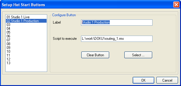
To define Hot Start Buttons, call the command from the menu. A dialogue opens, which can be used to define up to 14 Hot Start Buttons.
Please follow this description to create or change Hot Start Buttons:
In the left hand list, click on the entry which you would like to edit. A name for this button can be entered in the field Label. This label will be shown on the button and can have a maximum length of 20 characters.
![[Note]](../pics/note.gif)
Note If you do not enter a text in the field Label, this Hot Start Button will not be displayed!
Click the button. A file dialogue appears. Choose a routing script, which you would like to connect to the selected button. You can choose only RM4200D routing scripts, indicated by the suffix “.rms”.
If you would like to delete an already defined Hot Start Button, select the corresponding entry in the list, and click .
Proceed in the same way for all further Hot Start Buttons, which you would like to edit. After you have finished your work, click the OK button.
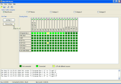
To use these Hot Start Buttons in the software, you need to switch them on. Therefore, call the command from the menu or press function key F10 on your computers keyboard. Activating the command or the function key F10 again switches off the Hot Start Buttons.
In the software, only such Hot Start Buttons will be shown, which are labelled with a name. If you right click in the Hot Start area, a context menu with two entries appears. Command opens the configuration dialog for Hot Start Buttons, command switches off the Hot Start Buttons.
![[Tip]](../pics/tip.gif) | Tip |
|---|---|
If you leave the mouse cursor above a specified Hot Start Button for a second, a tooltip will appear. It will display which script is assigned to the Hot Start Button. | |
By clicking a Hot Start Button, you immediately execute the assigned routing script.
With the “Scheduler” feature, you are able to automatically control router processes based on specified dates. You can configure singular or recurring events; the number of planable events is unlimited. Finally, you can also define, if a single crosspoint or a complex routing script is executed at a given date.
![[Important]](../pics/important.gif) | Important |
|---|---|
If you would like to use the Scheduler, you need to have a license for this feature. This license can be purchased separately. Please contact your DHD dealer. | |
To display the Scheduler, call the command in the menu.
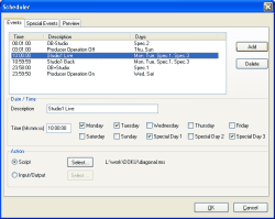
The Scheduler dialogue contains three register tabs: In the Events area, you can edit the planned events, in the Special Events area, up to three different lists of special days can be defined and the Preview area enables to check, which events are planned on which date.
In this register tab, you are able to edit your planned events. The list in the upper part of the dialogue contains all planned events in their chronological order. Each event is displayed with its execution time (Time column) and a short description (Description column). In the Days column is listed, on which days a process is performed.
To create a new switching process, proceed like this:
Click the button, to create a new event. A new event is inserted, which is selected automatically. The starting time for this event will be automatically pre-set to 00:00:00, which forces the entry to be displayed on the very top of the list.
In the Date/Time area, you enter details for the configured event. Enter a meaningful comment with a maximum length of 40 characters into the Description field. It will be displayed in the status bar of the main application window. Use the Time field to define an exact time for the switching process. This entry needs to be formatted like “hh:mm:ss”, hours must be entered from “00” to “23”. In a next step, use the checkboxes to choose those days, when the process should be executed. You may select every weekday as well as each of the available “Special Days”. If you change details of an event, the list of events will be refreshed according to these changes.
![[Important]](../pics/important.gif)
Important To plan an event for the current day (which means “today”), you need to select the checkbox for the present day. If not selected, the event will not be executed!
In the Action area, you choose what exactly should happen on a certain time: If you select the Script radiobutton, a routing script can be executed on the specified date. Click on the button to choose the desired script using a file dialogue. The script’s name will be shown in the Action area.
Use the Input/Output radiobutton, if you would like to set a single crosspoint. Click the button to open another dialogue, wherein you can choose input and output for this single crosspoint. If your assignment is done, it will also be shown in the Action area.
Create further events in the same way. Use the Preview tab to control whether your settings are correctly done.
If you would like to remove an already planned event, select the according entry in the list at first. Click the Delete button then. The event will be directly deleted without any confirmation!
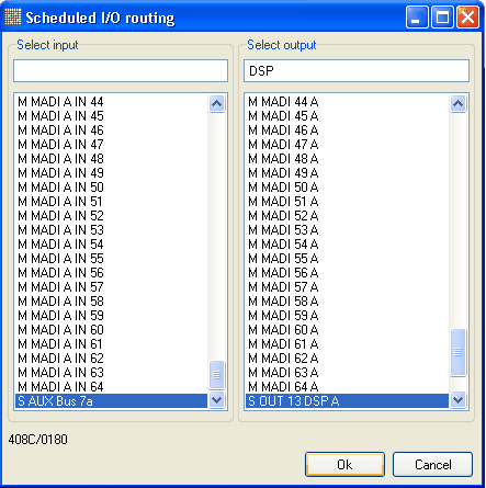
The following picture shows the dialogue to assign a single input to a specified output:
The left hand list displays all available inputs, the right hand list shows all available outputs. Use the text input field above the lists, to filter the displayed entries: enter any string to move the active selection to the first entry, which contains this string.
Select the input and the output you would like to connect, then click the OK button to store your selection.
![[Tip]](../pics/tip.gif) | Tip |
|---|---|
Use the filter functionality of the text input field to find the right entries in very long lists. If you would like to mute an output, which means to connect no signal to it, choose the very first entry None of the left hand list of input signals. With this selection, an existing coupling will be suspended. | |
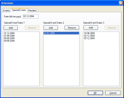
Occasionally, you would like to execute crosspoint switchings on specific, irregular days. In such cases, you can use this tab to create up to three lists for any date, on which a crosspoint processing should take place. These lists may be included by selecting the corresponding Special Days checkboxes while planning events. They are going to be used like usual weekdays: Switchings will be processed whenever current time and date is matching to a defined value in the activated lists.
To create a new entry in one of the lists, you first need to enter a date (formatted “DD.MM.YYYY”), using the Date field. Then click the button above the list, wherein this new entry should be placed. Finally, the new entry appears in the list.
To remove an entry from a list, select it with a mouse click. Then press the button to delete the selected entry from the list.
Use this register tab to see all switching processes of different days combined in one view. From the Select area, choose the tag you would like to monitor by using the radiobuttons on the left hand side of the dialogue. All planned events for this day will be listed, including their execution time, a description and the assigned routing script.
![[Note]](../pics/note.gif) | Note |
|---|---|
If you have not assigned a specified routing script to an event, but a simple action, no entry will be shown in the Script column. | |
