Table of Contents
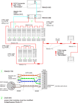
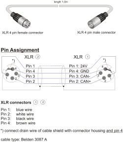
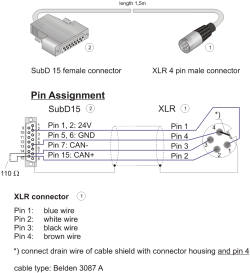
This section contains all information you need to wire the control modules of the RM4200D to each other and to the DSP frame. Please comply to these specifications, or the system may not run stable.
![[Important]](../pics/important.gif) | Important |
|---|---|
The total length of the CAN-Bus wiring must not exceed 60 metres! | |
![[Important]](../pics/important.gif) | Important |
|---|---|
The total length of the CAN-Bus wiring is the summed up length of all XLR-CAN-Bus cables in the system plus the length of the optional RJ45-network cable between the DSP Frame RM420-061/062/063/064 and the Power Supply Frame RM420-081/086! | |
Da es so wichtig ist, hier noch einmal in Deutsch:
![[Important]](../pics/important.gif) | Important |
|---|---|
Die Gesamtlänge des CAN-Busses darf 60m nicht überschreiten! | |
![[Important]](../pics/important.gif) | Important |
|---|---|
Die Gesamtlänge des CAN-Busses ist die addierte Länge aller im System vorhandenen XLR-CAN-Bus Kabel plus der Länge des optionalen RJ45-Netzwerkabels zwischen DSP-Frame RM420-061/062/063/064 und dem Netzteil-Frame RM420-081/086! | |


