Table of Contents
- 3.1. Basics
- 3.2. Boot Loader
- 3.3. Firmware
- 3.4. Config (Config data)
- 3.5. Setup (Snapshots of the System State)
- 3.6. Parameter Memory
- 3.7. Memory Access at System Reset
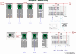
The RM4200D consists of several modules that are designed for different tasks and depending on the application are used in different combinations. Some of these modules are equipped with a microcontroller to control the functions of the respective module. This way, each module with a microcontroller can work on its own and has its own “intelligence”. However, the complete function of the RM4200D emerges only in cooperation of all modules. They communicate with each others via CAN bus that has to be wired appropriately. The following figure illustrates this:

As you can see from the figure, all modules with microcontrollers are connected to the CAN-bus. In addition, each module (except the table-top studio unit RM420-011) have a serial port. All commands transferred via CAN-bus are also available at the serial ports. In addition, the Communications Controller RM420-850 transfers these data also to the Ethernet port.
![[Tip]](../pics/tip.gif)
|
Tip |
|---|---|
|
If you want to use the serial port to connect a PC to a RM4200D, you can connect the PC to any serial port. The data traffic is identical at every port. This is sometimes helpful if e.g. a DSP frame is almost out of reach, but the ports of the control modules are easily accessible though. |
|
The following modules have a microcontroller:
-
All control modules (except fader overbridge modules). All modules making up the user interface of the RM4200D have their own micro controllers. This is true for all but the fader overbridge modules. These modules are “dumb” extensions of the circuit board in the fader module which also controls them. The microcontrollers in the fader modules read the current values of the elements of the user interface (buttons, faders, rotary knobs) and transfer them as control signals to the DSP frame. At the same time, they receive commands from the control system and control all display elements respectively – LEDs, alphanumeric displays. In fader modules with motor faders, they also control the motor fader if necessary.
-
DSP Controller RM420-851. This module is a slot-in card in the DSP frame, it controls an assigned DSP card RM420-848. The DSP controller acts as bridge between audio system and control system and transports the control commands from the CAN bus to the DSP cards. The other way round, it transfers e.g. messages of exceeding levels or correlation problems of stereo signals. Each DSP card in the DSP frame needs an assigned controller, allowing a maximum of three DSP controllers.
-
Communications Controller RM420-850. This module is a slot-in card in the DSP frame, too. There is only one such controller per DSP frame. It is used to control the DSP frame and also has an Ethernet port. Using this, the DSP frame can communicate via Ethernet with other RM4200D-systems or DHD software on PCs.
![[Note]](../pics/note.gif)
Note In the Communications Controller, there is also the memory for the Setups as well as the Parameter RAM with the current operating parameters of the system. Also, the license codes for the system are stored in here. If you exchange the Communications Controller RM420-850, you may have to transfer this information to the spare part. Please find more information in Part 3 of this manual, Toolbox 4 Configuration and Reference.
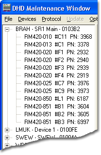
You can use the Toolbox4 Software to read out the structure of the modules in a RM4200D. To do this, use the command from the menu. In the tree view on the left, you see all RM4200D devices the software can currently access. Below the entry for each Device, you see all modules that have a microcontroller and can be accessed via the CAN bus.

The microcontroller is the interface between module hardware and the system. In order to be able to fulfill its task, it has to be programmed with the appropriate software. It is the software that carries out the real functions of the RM4200D.
Similar to a desktop PC, the controller software consists of several parts designed for certain tasks. These software parts are located in the memory of the microcontroller and are run as soon as the RM4200D is powered on.
The parts of the software parts directly dependent on each other, together they make up a memory image, the so calledMemory Map. The Memory Map consists of five parts:
-
Boot Loader. This is the basic “startup software”. It is executed by the micorocontroller as soon as its operating voltage is switched on or it is resetted. The Boot Loader can not be modified.
-
Firmware. This is the operating system of the modules. It is copied into the flash memory of the microcontroller using the Toolbox4 software. The firmware ontains all necessary functions that make up the RM4200D.
-
Config. This data describes the systemstructure and the interaction of its components. The Config is created in the Toolbox4 software and loaded in the RM4200D from there.
-
Setup. A setup is a “snapshot” of the current condition of the whole system or of some channels.
-
Parameter Memory. This part of the memory contains the current operating parameters for the RM4200D. It contains e.g. the currents values of the faders, setings for gain, filter and bus assignment of the separate channels.
In the following sections, read more about the parts of the Memory Map.