Chapter 3. List of Modules

Table of Contents

3.1. RM4200D DSP Frame
RM420-061 DSP Frame 3U/19“, empty
RM420-062 DSP Frame 6U/19“, empty
RM420-063 DSP Frame 6U/19“, empty
RM420-064 DSP Frame 9U/19“, empty
RM420-081 Power Supply Frame 3U/19“, empty
RM420-086 Power Supply Frame 3U/19“, empty
RM420-083 Power Supply 5V/75W, PFC
RM420-084 Power Supply 24V/75W, PFC
RM420-850 Communication Controller
RM420-851 DSP Controller
RM420-848L DSP Module, simple function
RM420-848M DSP Module, full function
RM420-421S Single AES10 MADI Submodule
RM420-422S Dual AES10 MADI Submodule
RM420-424S Delay Submodule,2 to 64 channels
RM420-111 Digital In/Out/GPIO Module,8 ch.
RM420-122 Mic/Headphone/GPIO Module, 4 ch.
RM420-123 Mic/Line/GPIO Module, 4 ch. iso.
RM420-222 Analog In/Out/GPIO Module, 4 ch.
RM420-223 Analog In/Out/GPIO Module, 4 ch.
RM420-311 GPIO Module, 12 Relays, 4 GPI
RM420-XLR-AA RJ45/XLR Adapter Panel 1U/19“
RM420-XLR-DD RJ45/XLR Adapter Panel 1U/19“
RM420-XLR-AD RJ45/XLR Adapter Panel 1U/19“
RM420-XLR-TR-AA RJ45/XLR Adapter Panel 1U/19“
3.2. RM4200D Control Modules
RM420-010 Main Module
RM420-011 Studio Panel
RM420-012 Central Module
RM420-013 Central Overbridge Panel
RM420-013L Central Overbridge Panel
RM420-014 Extended Central Module
RM420-020 Fader Module
RM420-020M Motor Fader Module
RM420-023 Fader Overbridge Panel
RM420-025 40 Pushbutton Panel
RM420-026 32 Pushbutton Panel
RM420-028 Extended Fader Overbridge Panel
RM420-029 Extended Fader Module
RM420-029B Extended Fader Module, PFL
RM420-029M Extended Motor Fader Module
3.3. RM4200D Router and Talkback Control Modules
RM420-018 Router Control Panel AES3 1U/19“
RM420-027 Talkback Panel
RM420-TB-HUB RJ45 Adapter Panel 1U/19“
RM420-078 8 LCD Pushbutton Panel
RM420-079 16 LCD Pushbuttons 1U/19“
3.4. Software
Toolbox 4
RM420-550 Routing Software
RM420-551 DSP Control Software
RM420-552 Setup Manager
RM420-553 Remote Control Software
RM420-554 MIDI Protocol Converter Software
RM420-561 Enhanced DSP Fixed Processing
3.5. Engineering Services
RM330-500 Configuration
RM330-502 Training
RM330-503 Acceptance Test

RM4200D DSP Frame

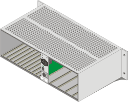
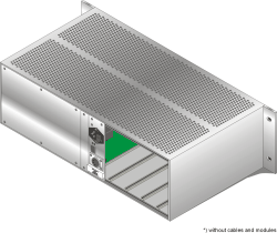
RM420-061 DSP Frame 3U/19“, empty

Figure 11: RM420-061

passive DSP backplane, 10 slots for:

  • 8 audio/GPIO modules

  • 1 DSP controller module

  • 1 DSP module or DSP/MADI module

passive mains backplane, 5 slots for:

  • 1 communication controller module

  • 4 power supplies 24V or 5V

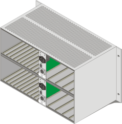
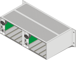
RM420-062 DSP Frame 6U/19“, empty

Figure 12: RM420-062

dual mains power inlet, 20 slots for:

  • 16 audio/GPIO modules

  • 2 DSP controller modules

  • 2 DSP modules or DSP/MADI modules

passive mains backplanes, 9 slots for:

  • 1 communication controller module

  • 2 x 4 power supplies 24V or 5V

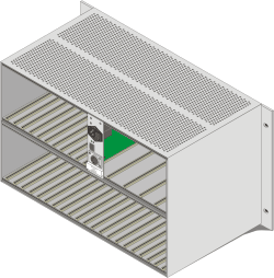
RM420-063 DSP Frame 6U/19“, empty

Figure 13: RM420-063

passive DSP backplane, 30 slots for:

  • 24 audio/GPIO modules

  • 3 DSP controller modules

  • 3 DSP modules or DSP/MADI modules

passive mains backplane, 5 slots for:

  • 1 communication controller module

  • 4 power supplies 24V or 5V

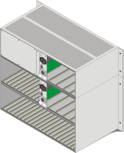
RM420-064 DSP Frame 9U/19“, empty

Figure 14: RM420-064

dual mains power inlet, 30 slots for:

  • 24 audio/GPIO modules

  • 3 DSP controller modules

  • 3 DSP modules or DSP/MADI modules

passive mains backplanes, 9 slots for:

  • 1 communication controller module

  • 2 x 4 power supplies 24V or 5V

RM420-081 Power Supply Frame 3U/19“, empty

Figure 15: RM420-081
  • for large consoles or long distances to DSP Frame

  • 4 slots for 24V power supplies (RM420-084 not included!)

  • CAN bus/ 24V XLR connector to console

  • CAN bus RJ45 connector to DSP Frame

RM420-086 Power Supply Frame 3U/19“, empty

Figure 16: RM420-086
  • for large consoles or long distances to DSP Frame, dual mains power inlet

  • 2 x 4 slots for 24V power supplies (RM420-084 not included!)

  • CAN bus/ 24V XLR connector to console

  • CAN bus RJ45 connector to DSP Frame

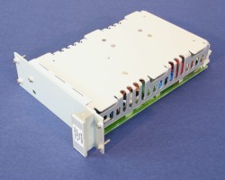
RM420-083 Power Supply 5V/75W, PFC

Figure 17: RM420-083
  • suitable for redundant operation

  • current share operation

  • range: 94V to 253V AC, 47 to 63Hz

  • necessary for operation of DSP Frame modules

  • power factor>0.98

  • Do not combine with RM420-085!

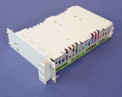
RM420-084 Power Supply 24V/75W, PFC

Figure 18: RM420-084
  • suitable for redundant operation

  • current share operation

  • range: 94V to 253V AC, 47 to 63Hz

  • necessary for operation of console

  • power factor>0.98

  • Do not combine with RM420-082!

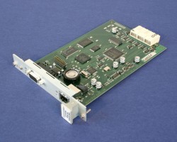
RM420-850 Communication Controller

Figure 19: RM420-850
  • 100baseTX Ethernet on RJ45

  • RS232 on SubD-9 connector

  • CAN bus

  • provides logic functions and setup memory

  • 1 module necessary for each RM4200D DSP Frame!

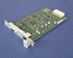
RM420-851 DSP Controller

Figure 20: RM420-851
  • RS232 on SubD-9 connector

  • CAN bus

  • 1 module necessary for each RM420-848 module!

  • operates on slots 9, 19, 29

RM420-848L DSP Module, simple function

Figure 21: RM420-848L
  • without submodule support and reduced routing channels

  • mixed operation with RM420-848M in one DSP Framenot supported

  • operates on slots 10 and 20

  • operation on slot 30not supported

  • 48kHz or 44.1kHz internal clock

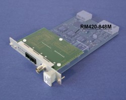
RM420-848M DSP Module, full function

Figure 22: RM420-848M
  • with submodule support and full routing capabilities

  • mixed operation with RM420-848L in one DSP Framenot supported

  • 1 socket for DHD Submodules

  • operates on slots 10, 20, 30

  • 48kHz or 44.1kHz internal clock

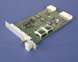
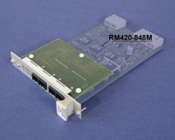
RM420-421S Single AES10 MADI Submodule

Figure 23: RM420-421S
  • 56 or 64 input channels and

  • 56 or 64 output channels

  • submodule for RM420-848M

  • fiberoptic receiver/transmitter

    • multimode, 50µm or 62.5µm, 1300nm

    • SC duplex connector

  • BNC TTL wordclock in or out

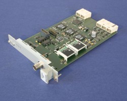
RM420-422S Dual AES10 MADI Submodule

Figure 24: RM420-422S
  • 2x 56 or 64 input channels and

  • 2x 56 or 64 output channels

  • submodule for RM420-848M

  • fiberoptic receiver/transmitter

    • multimode, 50µm or 62.5µm, 1300nm,

    • 2x SC duplex connector

  • dual or redundant MADI configurable

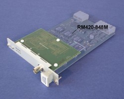
RM420-424S Delay Submodule,2 to 64 channels

Figure 25: RM420-424S
  • adjustable delay, number of channels selectable (2, 4, 8, 16, 32, 64)

  • 2 channels, each up to 21,8sec

  • 16 channels, each up to 2,7sec

  • 64 channels, each up to 0,7sec

  • submodule for RM420-848M

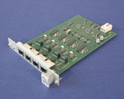
RM420-111 Digital In/Out/GPIO Module,8 ch.

Figure 26: RM420-111
  • 4 RJ45 connectors

  • 4 AES3/EBU/SPDIF inputs

  • 4 AES3/EBU/SPDIF outputs

  • 4 async. sample rate converters

  • 4 general purpose inputs, isolated

  • 4 general purpose outputs, isolated

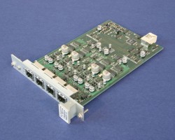
RM420-122 Mic/Headphone/GPIO Module, 4 ch.

Figure 27: RM420-122
  • 4 RJ45 Connectors

  • 4 el. balanced Mic/Line inputs with preamplifier, level 18dBu max.

  • phantom power 48V indiv. switchable

  • 2 stereo headphone outputs

  • 2 GPI, 4 GPO, 2 analog control in

RM420-123 Mic/Line/GPIO Module, 4 ch. iso.

Figure 28: RM420-123
  • 2 SubD-15 Connectors

  • 4 balanced Mic/Line inputs with preamplifier, level 18dBu max.

  • phantom power 48V indiv. switchable

  • isolated input stages

  • 4 GPI, 4 GPO

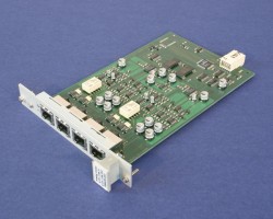
RM420-222 Analog In/Out/GPIO Module, 4 ch.

Figure 29: RM420-222
  • 4 RJ45 connectors

  • 4 line inputs, el. bal., 18dBu max.

  • 4 line outputs, el. bal., 18dBu max.

  • 4 general purpose inputs, isolated

  • 4 general purpose outputs, isolated

RM420-223 Analog In/Out/GPIO Module, 4 ch.

Figure 30: RM420-223
  • 4 RJ45 connectors

  • 4 line inputs, el. bal., 24dBu max.

  • 4 line outputs, el. bal., 24dBu max.

  • 4 general purpose inputs, isolated

  • 4 general purpose outputs, isolated

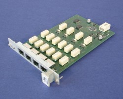
RM420-311 GPIO Module, 12 Relays, 4 GPI

Figure 31: RM420-311
  • 12 general purpose outputs, isolated with electro-mechanical relay

  • max. current 1A, max. voltage 30V

  • 4 general purpose inputs, isolated

  • 4 RJ45 connectors

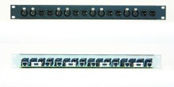
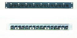
RM420-XLR-AA RJ45/XLR Adapter Panel 1U/19“

Figure 32: RM420-XLR_AA
  • for 8 RJ45 connections to 2 analog modules

  • 8 male XLR and 8 female XLR connectors stereo-paired

  • 4 SubD-9 GPIO connectors on the rear

  • 8 RJ45 connectors on the rear

  • 8 CAT5 patch cables 1m included

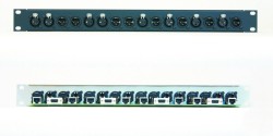
RM420-XLR-DD RJ45/XLR Adapter Panel 1U/19“

Figure 33: RM420-XLR-DD
  • for 8 RJ45 connections to 2 digital modules

  • 8 male XLR and 8 female XLR connectors on the front

  • 4 SubD-9 GPIO connectors on the rear

  • 8 RJ45 connectors on the rear

  • 8 CAT5 patch cables 1m included

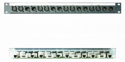
RM420-XLR-AD RJ45/XLR Adapter Panel 1U/19“

Figure 34: RM420-XLR-AD
  • for 8 RJ45 connections to 1 analog and 1 digital module

  • 8 male XLR and 8 female XLR connectors on the front

  • 4 SubD-9 GPIO connectors on the rear

  • 8 RJ45 connectors on the rear

  • 8 CAT5 patch cables 1m included

RM420-XLR-TR-AA RJ45/XLR Adapter Panel 1U/19“

Figure 35: RM420-XLR-TR-AA
  • for 8 RJ45 connections to 2 analog line level modules

  • 8 male XLR and 8 female XLR connectors stereo-paired

  • Lundahl Transformers LL2811, LL1545A

  • 4 SubD-9 GPIO connectors on the rear

  • 8 RJ45 connectors on the rear