Table of Contents
- 4.1. The Meaning of the LEDs
-
- I/O-Modules (RM420-111, -122, -123, -222, -223, -311)
- DSP-Controller RM420-851
- DSP Module RM420-848L, M
- DSP Modules RM420-848M with MADI Submodules RM420-421, -422
- Communication Controller RM420-850
- Power Supply Module RM420-845
- Power Supply Modules RM420-082, -083, -084, -085
- DSP Frames RM420-064, -063, -062, -061, Front Plate
- Control Modules RM420-010, -012, -014
- Fader Modules RM420-020, -029
Many modules of the RM4200D have LEDs, which indicate the current module status as well as the status of the whole device. The following information should help you to monitor the system status using the LEDs, also without having to use the DHD software.
Each I/O Module has two LEDs with the same function for all modules. The LEDs are located at the upper edge of the module above the RJ45 sockets.

|
|
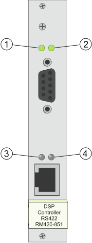
Exactly like the I/O modules, this module has two LEDs at the upper edge of the front plate. In addition, it has two LEDs in the lower part of this plate above the RJ45 socket. These LEDs have no function.
|
|
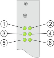
These DSP modules have six LEDs at the upper edge of the front plate.
|
|
These DSP Modules have eight LEDs at the upper edge of the front plate.

|
|
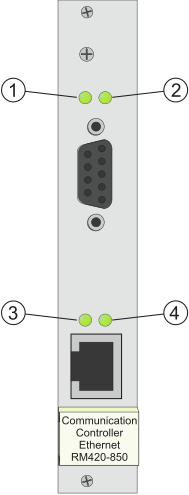
The Communication Controller has four LEDs, two at the upper edge of the front plate and two in the lower part above the RJ45 socket.
|
|
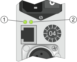
The power supply module is available in each DSP frame. It contains a power supply socket and the connector of the CAN bus, a 4-pin XLR socket. The additional RJ45-socket is designed to connect the data line of the CAN bus with an external power supply unit (RM420-081).
|
|
There are two different versioans of power supply units for the RM4200D. Currently, the modules RM420-084 (24V) and RM420-083 (5V) are used. Compared with their predecessing models, these modules have only one LED. The old version that is not used any longer was used by the modules RM420-082 (24V) and RM420-085 (5V). These modules are not manufactured any more and are available for exchange only. (see also Types of Power Supply Units and FAQ)

|
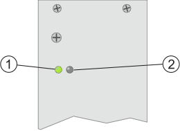
RM420-083, RM420-084 (new modules) The LED (1) on the front plate is on if the module is supplied with an input voltage (94 – 253VAC) and ready for operation. The LED is off if the module is not supplied with an input voltage or is faulty (DC Fail). |
||||
|
RM420-082, RM420-085 (old modules)�
|
||||
All DSP frames have several LEDs on their front plate that indicate the current operational status of the RM4200D.
![[Important]](../pics/important.gif)
|
Important |
|---|---|
|
In the course of its development, the function of different LEDs was modified due to requests by our customers. This way, different firmware revisions can contain different LED functions. In the following sections, the concerned functions are marked respectively. In any case, watch out which firmware version your RM4200D is using! You find the appropriate information in the corresponding sections on the firmware versions. |
|
![[Important]](../pics/important.gif)
|
Important |
|---|---|
|
The LEDs are controlled by the Communications Controller RM420-850. If this module is not completely initialised when switching on, the LEDs can indicate invalid conditions. In this case, wait some seconds until the display does not change any more. A similar effect can occur if the Communications Controller RM420-850 does not work properly. |
|
-
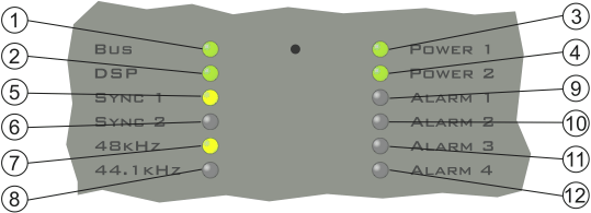
BUS (green): The CAN bus is ok.
-
DSP (green): All DSP available on the CAN bus work ok.
-
POWER 1 (green): The 24 V power supply works ok.
-
POWER 2 (green): The 5 V power supply works ok.
-
SYNC 1 (yellow): This LED is on if the system is synchronized by the synchronization source 1. You can configure the source in the Config.
-
SYNC 2 (yellow): This LED is on if the system is synchronized by the synchronization source 2. You can configure the source in the Config.
![[Note]](../pics/note.gif)
Note The LEDs SYNC 1 and SYNC 2 do never light both at the same time. If both LEDs are off, there is no signal at the configured synchronization sources. In this case, the system is synchronized internally. A change of the synchronization source during operation is marked with the entry „Synchronisation Source now <1 oder 2>“ in the log file.
-
48 kHz (yellow): The system is clocked with 48 kHz (measured value, 48 kHz +/- 500 Hz).
-
44.1 kHz (yellow): The system is clocked with 44,1 kHz (measured value, 44,1 kHz +/- 500 Hz).
![[Note]](../pics/note.gif)
Note The LEDs 48 kHz and 44.1 kHz do never light at the same time. If both LEDs are off, the RM4200D receives a varispeed clock from an external synchronization source which is out of the measurement range named above.
-
ALARM 1 (red): No function.
-
ALARM 2 (red): Since firmware version 5.3.26 without function. Before, faulty function in at least one DSP.
-
ALARM 3 (red): This LED is on if the clock frequency in at least one DSP differs from the target value by more than 20 Hz.
-
ALARM 4 (red): This LED is on if an audio link between the two backplanes is interrupted.
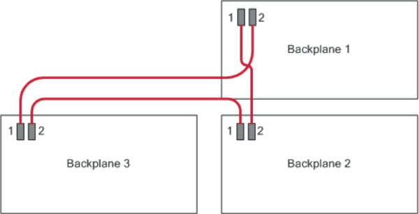
The DSP frame consists of several backplanes. A backplane is the basic circuit board that carries all modules. On each backplane, there is one DSP module with a DSP controller assigned to it. Each DSP module processes the signals of the I/O modules on the same backplane.
A DSP frame has either one (3 U case) or three backplanes (6 U case). The backplanes are interconnected using serial high speed busses, the so called audio links.The appropriate cables are located behind the front plate of the DSP frame. The connectors of the cables are equipped with clamps to avoid falling off.
The audio links are used to exchange the RM4200D audio signals between different DSP cards. In order to make this work properly, the backplanes must work together sychronized on the same clock. For this purpose, backplane 1 (top) is the master giving the clock. The other backplanes are slaves respectively.
If an “audiolink is interrupted” it means that the correct data exchange on the lines between the DSP cards is jammed due to synchonization problems between the backplanes. In the logfile of the DHD communication server, messages like “DSP Card <x> Link failed AudioLink <y>” appear.
This error status can have the following reasons:
-
The synchronization source is changed and the backplanes have not been synchronized yet.
-
At least one of the DSP controllers on the interconnected backplanes does not work at all or is faulty.
-
A DSP card has been removed and inserted during operation.
![[Important]](../pics/important.gif)
|
Important |
|---|---|
|
The LEDs are controlled by the Communications Controller RM420-850. If this module is not completely initialised when switching on, the LEDs can indicate invalid conditions. In this case, wait some seconds until the display does not change any more. A similar effect can occur if the Communications Controller RM420-850 does not work properly. |
|
-
BUS (green): The CAN bus works ok.
-
DSP (green): All DSPs available on the system work ok.
-
POWER 1 (green): The 24 V power supply works ok.
-
POWER 2 (green): The 5 V power supply works ok.
-
SYNC 1 (yellow): This LED is on if the system is synchronized by the synchronization source 1. You can configure the source in the Config.
-
SYNC 2 (yellow): This LED is on if the system is synchronized by the synchronization source 2. You can configure the source in the Config.
![[Note]](../pics/note.gif)
Note The LEDs SYNC 1 and SYNC 2 do never light both at the same time. If both LEDs are off, there is no signal at the configured synchronization sources. In this case, the system is synchronized internally. A change of the synchronization source during operation is marked with the entry „Synchronisation Source now <1 oder 2>“ in the log file.
-
48 kHz (yellow): The system is clocked with 48 kHz (measured value, 48 kHz +/- 500 Hz).
-
44.1 kHz (yellow): The system is clocked with 44,1 kHz (measured value, 44,1 kHz +/- 500 Hz).
![[Note]](../pics/note.gif)
Note The LEDs 48 kHz and 44.1 kHz do never light at the same time. If both LEDs are off, the RM4200D receives a varispeed clock from an external synchronization source which is out of the measurment range named above.
-
ALARM 1 (red): Nofunction.
-
ALARM 2 (red): No function.
-
ALARM 3 (red): This LED is on if the clock frequency in at least one DSP differs from the target value by more than 20 Hz.
-
ALARM 4 (red): This LED is on if an audio link between two backplanes is interrupted.
The DSP frame consists of several backplanes. A backplane is the basic circuit board that carries all modules. On each backplane, there is one DSP module with a DSP controller assigned to it. Each DSP module processes the signals of the I/O modules on the same backplane.
A DSP frame has either one (3 U case) or three backplanes (6 U case). The backplanes are interconnected using serial high speed busses, the so called audio links.The appropriate cables are located behind the front plate of the DSP frame. The connectors of the cables are equipped with clamps to avoid falling off.
The audio links are used to exchange the RM4200D audio signals between different DSP cards. In order to make this work properly, the backplanes must work together sychronized on the same clock. For this purpose, backplane 1 (top) is the master giving the clock. The other backplanes are slaves respectively.
If an “audiolink is interrupted” it means that the correct data exchange on the lines between the DSP cards is jammed due to synchonization problems between the backplanes. In the logfile of the DHD communication server, messages like “DSP Card <x> Link failed AudioLink <y>” appear.
This error status can have the following reasons:
-
The synchronization source is changed and the backplanes have not been synchronized yet.
-
At least one of the DSP controllers on the interconnected backplanes does not work at all or is faulty.
-
A DSP card has been removed and inserted during operation.
![[Important]](../pics/important.gif)
|
Important |
|---|---|
|
The LEDs are controlled by the Communications Controller RM420-850. If this module is not completely initialised when switching on, the LEDs can indicate invalid conditions. In this case, wait some seconds until the display does not change any more. A similar effect can occur if the Communications Controller RM420-850 does not work properly. |
|
-
BUS (green): The CAN bus works ok.
-
DSP (green): All DSPs available in the system work ok.
-
POWER 1 (green): The 24 V power supply works ok.
-
POWER 2 (green): The 5 V power supply works ok.
-
SYNC 1 (yellow): This LED is on if the system is synchronized by the synchronization source 1. You can configure the source in the Config.
-
SYNC 2 (yellow): This LED is on if the system is synchronized by the synchronization source 2. You can configure the source in the Config.
![[Note]](../pics/note.gif)
Note The LEDs SYNC 1 and SYNC 2 do never light both at the same time. If both LEDs are off, there is no signal at the configured synchronization sources. In this case, the system is synchronized internally. A change of the synchronization source during operation is marked with the entry „Synchronisation Source now <1 oder 2>“ in the log file.
-
48 kHz (yellow): The system is clocked with 48 kHz (measured value, 48 kHz +/- 500 Hz).
-
44.1 kHz (yellow): The system is clocked with 44,1 kHz (measured value, 44,1 kHz +/- 500 Hz).
![[Note]](../pics/note.gif)
Note The LEDs 48 kHz and 44.1 kHz do never light at the same time. If both LEDs are off, the RM4200D receives a varispeed clock from an external synchronization source which is out of the measurment range named above.
-
ALARM 1 (red): Power Supply Failed. This LED is on if at least one power supply unit of the DSP frame has failed.
-
ALARM 2 (red): External Power Supply Failed. This LED is on if at least one power supply unit in the external power unit RM420-081 has failed. (The external power unit is optional and not with every RM4200D available!)
-
ALARM 3 (red): Temperature too high. The control modules of the console have a sensor monitoring the temperature on the microcontroller. If this rises over 60 ºC , the LED lights up. (Since firmware version 5.5.7, this threshold value has been increased to 65 ºC.)
-
ALARM 4 (red): Control Module Voltage too low. This LED is on if in at least one module of the console the supply voltage is lower than 20 V DC.
![[Important]](../pics/important.gif)
|
Important |
|---|---|
|
All alarm messages create entries in the log file accordingly. This is also true for all messsages displayed using LEDs up to firmware version 5.5.0.) |
|
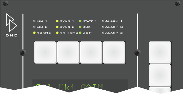
The status of the RM4200D is not only indicated at the DSP frame, but also on the central control modules RM420-010, -012 and -014. The LEDs are located at the top edge of the module.
![[Note]](../pics/note.gif)
|
Note |
|---|---|
|
Although there are LEDs labelled ALARM in the console, they are not used. The reason for this is that some alarm states do only occur very rarely and only for a short time, which is not critical. These conditions are not indicated at the console to not irritate the user. |
|
The LEDs in the module RM420-010 indicate the following conditions:
| LIM 1: | No function. |
| LIM 2: | No function. |
| SYNC 1: | This LED is on if the system is synchronized by the synchronization source 1. You can configure the source in the Config. |
| SYNC 2: | This LED is on if the system is synchronized by the synchronization source 2. You can configure the source in the Config. |
| 48 kHz: |
The system is clocked with 48 kHz (measured value, 48 kHz +/- 500 Hz). |
| 44.1 kHz: | The system is clocked with 44,1 kHz (measured value, 44,1 kHz +/- 500 Hz). |
| State 1: | No function. |
| BUS: | The CAN bus works ok. |
| DSP: | All DSPs available in the system work ok. |
| ALARM1: | No function. |
| ALARM2: | No function. |
| ALARM3: | No function. |
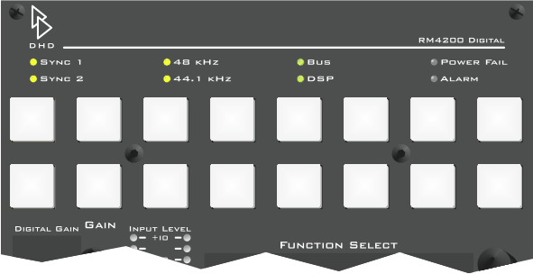
The LEDs in the control modules RM4200D 420-012 and -014 indicate the following conditions:
| SYNC 1: | This LED is on if the system is synchronized by the synchronization source 1. You can configure the source in the Config |
| SYNC 2: | This LED is on if the system is synchronized by the synchronization source 2. You can configure the source in the Config |
| 48 kHz: |
The system is clocked with 48 Hz (measured value, 48 kHz +/- 500 Hz). |
| 44.1 kHz: | The system is clocked with 44,1 kHz (measured value, 44,1 kHz +/- 500 Hz). |
| BUS: | The CAN bus work ok. |
| DSP: | All DSPs available in the system work ok. |
| POWER FAIL: | No function. |
| ALARM: | No function. |
Each fader of a module RM420-20 or RM420-029 has several displays for certain states. The following table shows the details.
| OVERLOAD/ERR: LED in two colors | |||
| Signal type | color | Meaning | |

|
analog | green | Signal available, input not overdriven (RM420-020). |
| red | Signal available, input overdriven (RM420-020). | ||
| off | No function for RM420-029, since level indicator located next to the fader. | ||
| digital | green | Valid signal available (RM420-020). | |
| red | No valid signal available | ||
| off | Valid signal available (RM420-029). | ||

|
GAIN/PHASE:
This LED lights yellow if one or more of these conditions are true:
|
||
|
PAN/BAL:
This LED lights yellow if one or more of these conditions are true:
|
|||
|
EQs:
This LED lights yellow if one or more filters are active (ON):
|
|||
|
DYNAMICS:
This LED lights yellow if the dynamic processing is active. The following functions make the LED light up:
|
|||
|
PROGRAM 1:
The fader signal is switched on program bus 1. |
|||
|
PROGRAM 2:
The fader signal is switched on program bus 2. |
|||
|
AUX 1-4:
The fader signal is switched on Aux Bus 1-4. |
|||
