A setup is a collection of parameters, which are used in the context of a configuration in order to adapt DSP functions. This collection includes for instance parameters like amplification of a signal (Gain) or limiter threshold. In the RM4200D, there are Mixer Setups and Channel Setups. A Mixer Setup comprises the parameters for all configured Fader Channels of the entire RM4200D, whereas a Channel Setup contains only parameters for one individual Fader Channel. Moreover, it has no direct connection to the configured Fader Channels.
In order to keep saving and loading as short as possible, only values differing from a certain default value are stored in setups. The following chart shows which parameters are stored in Setups and which default values apply to them.
| DSP-Funktion | Parameter | Wertebereich | Vorgabe-wert | Mixer Setup | Channel Setup |
|---|---|---|---|---|---|
| GAIN | Gain (digital) | -20 dB to 20 dB | 0 dB | + | + |
| AGain (analog) | 0 dB to 50 dB | 0 dB | + | + | |
| Phasereverse | OFF or ON | OFF | + | + | |
| Phantom | OFF or ON | OFF | + | + | |
| LIMITER (Device 1) | LIM1 | OFF or ON | OFF | + | + |
| Threshold | -20 dB to 20 dB | 20 dB | + | + | |
| Release | 3 dB/s to 20 dB/s | 6 dB/s | + | + | |
| COMPRESSOR | COMP1 | OFF or ON | OFF | + | + |
| Threshold | -50 dB to 10 dB | 0 dB | + | + | |
| Gain | 0 dB to 30 dB | 0 dB | + | + | |
| Ratio | 1.0:1 to 5.0:1 | 1.0:1 | + | + | |
| Attack | 0.2 ms to 50 ms | 0.2 ms | + | + | |
| Release | 0.05 s to 10 s | 0.05 s | + | + | |
| EXPANDER (Device1) | EXP1 | OFF or ON | OFF | + | + |
| Threshold | -50 dB to 10 dB | 0 dB | + | + | |
| Gain | 0 dB to 30 dB | 0 dB | + | + | |
| Ratio | 1.0:1 to 3.0:1 | 1.0:1 | + | + | |
| Attack | 0.05 s to 10 s | 0.05 s | + | + | |
| Release | 0.2 ms to 50 ms | 0.2 ms | + | + | |
| EQUALIZER (Device 1-4) | EQ1-4 | OFF or ON | OFF | + | + |
| Gain | -15 dB to 15 dB | 0 dB | + | + | |
| Frequency | 22 Hz to 20000 Hz | 1000 Hz | + | + | |
| Quality | 0.3 Oct to 3.0 Oct | 1.0 Oct | + | + | |
| Filter Type | Bell, Notch, High & Low Shelving | Bell | + | + | |
| AUTOMATIC GAIN CONTROL (Device 1) | AGC1 | OFF or ON | OFF | + | + |
| Velocity | 0.3 dB/s to 1.5 dB/s | 1.5 dB/s | + | + | |
| Gain | 5 dB to 30 dB | 20 dB | + | + | |
| Level | -20 dB to 20 dB | 20 dB | + | + | |
| Threshold | -40 dB to -20 dB | -20 dB | + | + | |
| SUBSONIC (Device 1) | SUBS1 | OFF or ON | OFF | + | + |
| Frequency | 32 Hz to 200 Hz | 50 Hz | + | + | |
| DEESSER (Device 1) | DeEs1 | OFF or ON | OFF | + | + |
| Ratio | 1.0:1 to 4.0:1 | 1.0:1 | + | + | |
| Threshold | 1.0 to 1.8 | 1.0 | + | + | |
| Bandwidth | 0.2 to 0.5 | 0.2 | + | + | |
| DEESSER LIGHT (Device 1) | DeEs1 | OFF or ON | OFF | + | + |
| Frequency | 1000 Hz to 20000 Hz | 4000 Hz | + | + | |
| Threshold | -40 dB to 10 dB | 0 dB | + | + | |
| NOISE GATE (Device 1) | GATE1 | OFF or ON | OFF | + | + |
| Threshold | -50 dB to -10 dB | -10 dB | + | + | |
| Attenuation | 0 dB to 30 dB | 0 dB | + | + | |
| Attack | 0.2 ms to 50 ms | 0.2 ms | + | + | |
| Release | 0.05 s to 10 s | 0.05 s | + | + | |
| FILTER (Device 1, 2) | FILT | OFF or ON | OFF | + | + |
| Type | Low Pass or High Pass | Low Pass | + | + | |
| Frequency | 22 Hz to 20000 Hz | 1000 Hz | + | + | |
| Order | 1 to 10 | 1 | + | + | |
| STEREO WIDTH CONTROL (Device 1) | Width | 0.0 to 2.0 | 1.0 | + | |
| Direction | L10> 0> 10R> -0 | 0 | + | ||
| Type | XY or MS | XY | + | ||
| Sign | + or - | + | + | ||
| DELAY (Device 1) | Delay | OFF or ON | OFF | + | |
| Length | 0 ms to 21800 ms (with 2 Ch.) | 0 ms | + | ||
| PANORAMA/BALANCE | Pan (mono) | L10 to 10R | 0 | + | |
| Bal (stereo) | L10 to 10R | 0 | + | ||
| Matrix (stereo) | L>L R>R, L>L L>R, R>L R>R, R>L L>R, Mono, Mono -3 dB, Mono -6 dB | L>L R>R | + | ||
| MPX OUT | Gain | -30 dB to 10 dB | 0 dB | + | |
| Outsel | OFF or ON | OFF | + | ||
| Outsel Source | Eintrag 0 to 249 | 0 | + | ||
| CF Cut | OFF or ON | OFF | + | ||
| N/N-1 | N-1 Mix or N Mix | N-1 Mix | + | ||
| MPX IN | Preparation | OFF or ON | OFF | + | |
| Gain | -15 dB to 15 dB | 0 dB | + | ||
| PROGRAM BUS | Program Device Nr. | OFF or ON | ON | + | |
| AUX BUS | Aux Device Nr. | OFF or ON | ON | + | |
| Gain | -oo dB to +15 dB | 0 dB | + | ||
| Type | AfterFader, PreFader, PreSwitch | AfterFader | + | ||
| VCA (from firmware version 5.5.0) | VCA | Group 1..8 | - | + |
Mixer Setups additionally contain further information:
Channel Assignment: Assignment of the configured Fader Channels to existing Hardware Faders.
Routing: Assignment of sources to so-called routing selectors (optional from Firmware 5.5.0)
Fader Values: Position of Fader Potentiometers (optional from Firmware 5.5.0, suggested for production operation only)
Show Timer in Channel Display: Information about if a timer is shown in the Channel Display (only for RM420-020 from Firmware 5.5.0 on).
Parameters in a Mixer Setup always have a fixed relation to configured Fader Channels, independent of their position on the console. The fixed relation between the information in the setup and the information in the configuration file is characterized by the defined channel number. On the configuration of a Fader Channel, the channel number is assigned automatically in ToolBox4 (e.g. “CH1 Tel1”) and reappears in a Mixer Setup (e.g. as Current Channel Setting Nr. 1 - Tel1).
In contrast to a Mixer Setup, a Channel Setup does not have a fixed relation to a particular Fader Channel. Thus the parameters stored in a Channel Setup can be applied to any Fader Channel. However, there are two peculiarities:
On the one hand, you can load a Channel Setup to an active, open Fader Channel. There you may change the parameters for DSP functions (for instance limiter or compressor settings). However, you must not interrupt or change an active bus routing or set a new routing.
On the other hand, a flexibly applicable Channel Setup has to be mono/stereo compatible. When loading, you only may change parameters without influence on the direction of the signal. Thus, for instance balance settings are not interpreted. The chart Parameters in Mixer Setups and Channel Setups shows precisely which parameters are stored in Mixer Setups and which in Channel Setups. (See “Which Data are Stored in Setups” on page 137.)
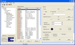
In the Setup Content window you can view
and examine the contents of a setup. For opening this window, please
first select a Mixer Setup or Channel Setup in the Device or a Setup
file (*.dms or *.dcs)
on the PC. Then click on the thereby activated
 on (View) on the divider in the centre
of the main window. By clicking the button in the view Backup, you can also view
the entire contents of a backup file in the Setup Content window.
The amount of the data shown in the Setup Content window varies depending on the kind of the selected Setup. While a Channel Setup has a manageable size, the bulk of information in a Mixer Setup file can appear quite complex at first sight.
Of help is the hierarchical representation of the setup parameters in a tree structure. By selectively expanding and collapsing individual branches, you can easily navigate to the wanted parameters.
Collapsing an expanded branch: Click the
 -icon or
double-click the entry to its right side.
-icon or
double-click the entry to its right side.Expanding a collapsed branch: Click the
 - icon or double-click the entry to its
right side.
In order to expand the entire tree structure with all branches, hit the button . Depending on the number of parameters stored in the setup, the list in the Setup Content window might then become very long. Hitting the button closes all branches.
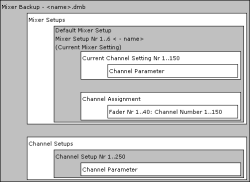
For better understanding please see the below showcase figure of the hierarchical Nesting Principle of Setups and Parameters.
All grey sections can be accessed with the aid of the Setup Manager. You can back them up in files on the PC or copy them from the PC to an RM4200D.
The type Mixer Backup and its file name are the root of the parameter list. The list contains all Mixer Setups and Channel Setups with parameters differing from the default values.(See “Which Data are Stored in Setups” on page 137.) Mixer Setups or Channel Setups without any content are not displayed. Neither do Mixer Backup files contain a copy of the Current Mixer Setting, i.e. the mixer settings that are active at the moment of saving.
![[Note]](../pics/note.gif) | Note |
|---|---|
User-specific names of Mixer Setups and Channel Setups are stored in a Mixer Backup. However, they are only restored into the RM4200D if the Channel Setups segment is activated on restoring. (See “Restore Device” on page 134.) | |
The root of the parameter list shows the type Mixer Setup, the number of the Mixer Setup (Nr 1..6) and its name. In the case of a *.dms file, the name matches the file name. In the case of a read-out Mixer Setup, the name corresponds to the setup name.
Beneath the root, the size (in Byte) of all Channel Settings stored in the Mixer Setup is shown under Size of all Channel Settings. This is followed by the Channel Settings stored in the Mixer Setup. If no Channel Settings are stored, i.e. all parameters equal their default value, Size of all Channel Settings shows 0 Byte.
Channel Settings are displayed, if at least one parameter of the respective channel differs from the intended default parameters. In this case, not only the differing parameter is shown, but also all other parameters relating to the same DSP process. If for instance the compressor threshold was changed, this value and all other compressor parameters are displayed.
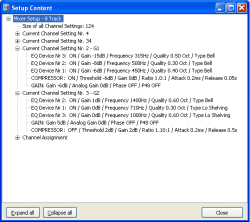
Example: The compressor threshold of channel“ G1”was changed to -6dB via the console. All other parameters remain untouched. With the aid of the Setup Manager, you can now read out the following values:

If you change parameters of other DSP processes of channel “G1”, they are also added to the list.

The order of the displayed parameters does not accord to the order designated in the configuration. Instead, the DSP process with the last parameter change is added to the bottom of the list. At first sight, the shown parameters may therefore appear to be arranged at random. Yet, their position is irrelevant for the usage of values in the DSP.
The branch Channel Assignment shows the assignments of Fader Channels to configured, physical faders. Physical faders without assigned Fader Channels are not displayed.
![[Note]](../pics/note.gif) | Note |
|---|---|
User-specific Mixer Setup names are not stored in a Mixer Setup file, hence they cannot be restored into the RM4200D. After copying individual Mixer Setups from PC into an RM4200D, or after a partial restore process, please check if setup names need to be adjusted. | |
The root of the parameter list shows the type Channel Setup, the number of the Channel Setup (Nr 1..6)and its name. In the case of a *.dcs file, the name matches the file name. In the case of a read-out Channel Setup, the name corresponds to the setup name.
The actual parameters are displayed below. Channel Setup parameters are displayed, if at least one parameter of the respective channel differs from the intended default parameters. In this case, not only the differing parameter is shown, but also all other parameters relating to the same DSP process. If for instance the compressor threshold was changed, this value and all other compressor parameters are displayed.
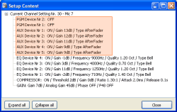
Example: The compressor threshold of channel“ G1”was changed to -6dB via the console. All other parameters remain untouched. With the aid of the Setup Manager, you can now read out the following values:

If you change parameters of other DSP processes of channel “G1”, they are also added to the list.

The order of the displayed parameters does not accord to the order designated in the configuration. Instead, the DSP process with the last parameter change is added to the bottom of the list. At first sight, the shown parameters may therefore appear to be arranged at random. Yet, their position is irrelevant for the usage of values in the DSP.
![[Note]](../pics/note.gif) | Note |
|---|---|
User-specific Channel Setup names are not stored in a Channel Setup file, hence they cannot be restored into the RM4200D. After copying individual Channel Setups from PC into an RM4200D, please check if setup names need to be adjusted. | |
If a setup, for example containing a compressor function, was copied into a Device without configured compressor function, the parameters for the not included compressor function remain without effect after loading. This applies for all DSP functions, for which parameters can be stored in setups.
![[Important]](../pics/important.gif) | Important |
|---|---|
The RM4200D software does not interpret parameters that relate to non-configured functions. | |
Parameters without respective function will appear in setups when
the function has ceased to exist due to a configuration change. Example: A Mixer Setup contains the information for Channel 1 that the signal is mixed with+5 db onto the Aux Bus 3 in the “PreFader” mode. Due to a configuration change, Aux Bus 3 is removed. The parameters for the signal mixing of Channel 1 in Aux Bus 3 are still included in the Mixer Setup, yet they are without effect. These parameters would only become reactivated in the case of a further change, when Aux Bus 3 would be added again.
the setup originates from another console with a different configuration.
In both cases, only those parameters are used, which have an intended function in the configuration of the Device. All parameters without respective function are ignored. However, they remain in the setup until it is overwritten by a renewed saving process via key functions on the console.
![[Note]](../pics/note.gif) | Note |
|---|---|
In order to avoid misunderstandings you should immediately overwrite parameters without respective function by renewed saving of the respective setup(s) with key functions on the console. | |
If you use the Setup Manager without connection to an RM4200D or if the connection is interrupted during your work, the Setup Manager cannot provide any information about channel names or setup names. You can still open e.g. Mixer Setup files (*.dms) on your hard disk. Yet, without an active connection, only the channel number of the included parameters is shown; the name of the according channel cannot be displayed.
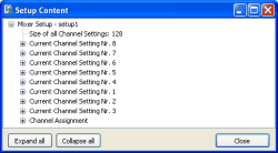
In networks with several RM4200D Devices, the following situation may occur:
You have connected the Setup Manager to a particular Device. In the meantime, you would like to view a Mixer Setup file (*dms), which was copied to the PC from a different Device. In this case, the configured Fader Channels in the connected Device might easily differ with respect to number and kind from those in the opened Mixer Setup file. Consequently in the Setup Content window, some channel parameters of the Mixer Setup file bear names, but some do not.
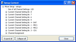
Nameless parameter sets may result not only from differences between online data and offline data. Mixer Setups within an RM4200D can contain nameless Fader Channels, also. This always occurs when
a Mixer Setup file with parameter sets for channels that are not configured in the system has been copied in an RM4200D.
one or more channels with existing parameter sets in the setup are deleted from the configuration.
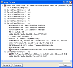
From time to time, Mixer Setups and Channel Setups can contain faulty parameters. In the Setup Content window, faulty parameters bear a red warning icon and additional debug information.
Errors in setup parameters are infrequent and mostly originate from two reasons:
a. A function and its parameters are unknown to the Setup Manager: In the course of the further development of the RM4200D, the amount of the functions and parameters stored in the setups has grown continuously. New functions will be regarded in an updated version of the Setup Manager. If certain functions and their parameters are unknown to the currently used Setup Manager version, the according line is displayed as faulty.
![[Note]](../pics/note.gif)
Note For troubleshooting you should check if the version of the currently used Setup Manager is compatible with the firmware version of your RM4200D. If you are not sure which Setup Manager version matches the firmware of your RM4200D, please use the latest version. It can be obtained from your DHD dealer or from DHD directly. Please then use the newer version for renewed setup read-out.
One or more parameters of a known function are invalid: All parameters of functions stored in setups are only valid within defined ranges of values. (See “Which Data are Stored in Setups” on page 137.)As soon as a parameter of any function is out of its validity range, the according line in the list is displayed as faulty. A potential reason for individual faulty parameters are terminated saving or loading processes, mostly under the use of chip cards, when those are removed from the card reader during access.
![[Note]](../pics/note.gif)
Note For troubleshooting please first check if the version of the currently used Setup Manager is compatible with the firmware version of your RM4200D. In case of doubt, always use the newest Setup Manager version. If faulty values still occur when you use the newest version of the Setup Manager, overwrite or save the setup anew. Please first make sure that the parameters to be stored are not faulty already (Current Mixer Settings or Mixer Setup File, *.dms).
A previous paragraph points out that on loading Channel Setups, only parameters may be interpreted that do not influence bus routings and are mono/stereo compatible. (See “The Difference between Mixer Setup and Channel Setup” on page 142.)This is because, as already mentioned, Channel Setups can also be loaded onto “open” channels. There, with respect to On-Air operation, active bus routings must be prevented from being switched off.
Comparing the actually read-out parameters of a Channel Setup with the information about routing parameters stated above, you will notice that, contrary to expectations, routing information did have been stored in Channel Setups (marked red).
In fact, routing parameters are stored in Channel Setups as well as in Mixer Setups, in which parameter sets are known to have a fixed assignment to a Fader Channel.
This results from the fact that, in the moment of saving, the software does not differentiate between the data structures. Discrimination between actual Channel Setups and channel parameters of a Mixer Setup does not take place until loading; and then the respective parameters are filtered.
