![[Important]](../pics/important.gif)
|
Important |
|---|---|
|
In addition to the specifications listed here, you find information on the modules and their connections in Part 1 (List of Modules) and Part 5 (Installation Guide) of this manual. |
|
-
Reference level digital: 0 dbFS = full scale modulation
-
Range of frequency for measurement: 20 Hz...20 kHz
-
Latency (Digital In to Digital Out, with SRC): typ. 1,5 ms
| Standard: | AES3/EBU + S/PDIF (configurable in software) |
| Sample rate converter (SRC): | avaiable, can be switched off |
| Sample frequency range (SRC): | 30 kHz ... 100 kHz |
| Frequency offset (with SRC): | < 0.02 dB |
| Input impedance: | 110 Ohm (AES/EBU), 75Ohm (S/PDIF) |
| Dynamic range (24 bit): | 140dB |
| THD+N (24 bit with SRC): |
< -120 dB (-1 dBFS, at 0dB amplification) < -140 dB (-60 dBFS, at 0dB amplification) |
| Jitter immunity: | > 40 ns |
| Standard: | AES3/EBU, S/PDIF (alternatively) |
| Ouput impedance: | 110 Ohm (AES/EBU), 75Ohm (S/PDIF) |
| Dynamic range (24 bit): | 144dB |
| Dither (configurable): | off, 16, 20, 24 Bit |
| Jitter (internal system synchronization) | < 2 ns (peak) |
| GPI control inputs (optocoupler, DC-insulated): | external input voltage 4V...24V (DC), 4mA |
| 4 GPO switching outputs (DC-insulated): | max. 0.2A / 30V DC / 25V AC |
-
Reference level analog: 0 dbU = 0.775 V (RMS)
-
Reference level digital: 0 dbFS = full scale modulation
-
Frequency range for measurements: 20 Hz...20 kHz
-
Sampling frequency: 44,1 KHz...48 kHz
-
Latency (Analog In to Analog Out): typ. 1 ms
|
Maximum input level: |
18 dbU (electronically balanced) |
| Frequency offset: | < 0,5 dB |
|
Amplification analog (in 5dB increments): |
0 dB...50 dB |
| Input impedance: | approx. 8 kOhm |
| Converter technology: | 24 bit, (64 x Oversampling Sigma-Delta) |
| Dynamic range: | 106 dB typical (A-rated) |
| THD+N: |
< -80 dB (-1 dBFS, at 0dB Analog Gain) < -98 dB (-60 dBFS, at 0dB Analog Gain) |
| Unbalance attenuation: | > 60 dB |
| Crosstalk: | < -90 dB |
| Input noise: |
< -126 dBu (200 Ohm source impedance, 50dB Analog Gain) |
|
Maximum output level (Headphones unsymmetrical): |
15 dbU |
| Frequency offset: | < 0,3 dB |
| Output impedance: | ca. 17 Ohm |
|
Load impedance Outputs short-circuit proof: |
≥ 80 Ohm |
| Converter technology: | 24 bit, (128 x Oversampling Sigma-Delta) |
| Dynamic range(24 bit): | 108 dB typical (A-rated) |
| THD+N (24 bit with SRC): |
< -82 dB (-1 dBFS) < -104 dB (-60 dBFS) |
| Crosstalk: | < -90 dB |
| DC voltage offset: | < 10 mV |
|
2 analog control inputs (ACI - Analog Control Input): |
|
| 2 GPI-control inputs: |
|
| 4 GPO-switching outputs: |
|
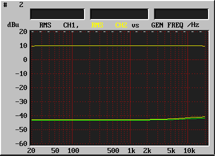
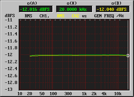
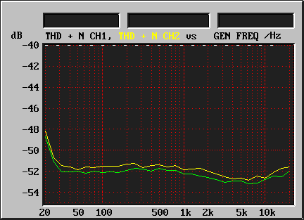
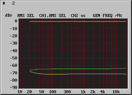
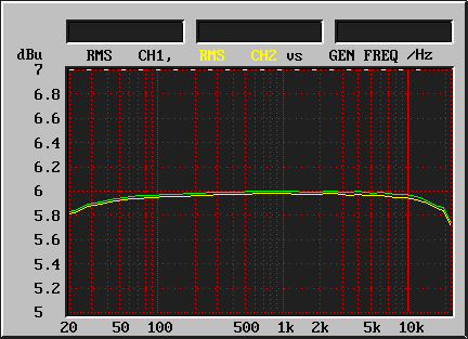
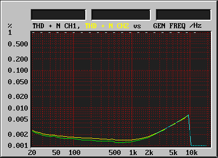
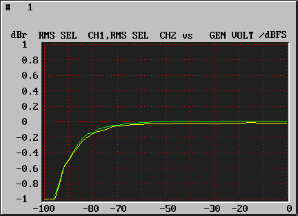
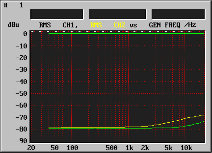
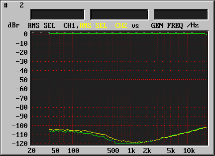
The following diagrams were recorded with an Audio Precision System One analyzer.
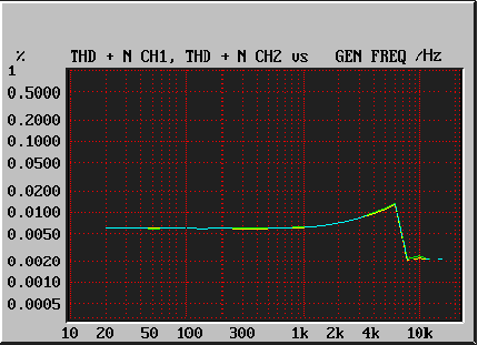
In the course of its history, DHD has developed several revisions of this module. The basic functions of these revisions are similar; but some parameters have better measurement values in later revisions. The differences are marked in the following list.
The module RM420-223 is identical with the module RM420-222, but it has a higher maximum input level.
![[Note]](../pics/note.gif)
|
Note |
|---|---|
|
You can exchange modules of different revisions without any problems. |
|
-
Reference level analog: 0 dbU = 0.775 V (RMS)
-
Reference level digital: 0 dbFS = full scale modulation
-
Frequency range for measurements: 20 Hz...20 kHz
-
Sample frequency: 44,1 KHz...48 kHz
-
Latency (Analog In to Analog Out): typ. 1 ms
|
Maximum input level: |
|
| Frequency offset: | < 0,1 dB |
| Input impedance: | approx. 10 kOhm |
| Converter technology: |
|
| Dynamic range: |
|
| THD+N at -1 dBFS: | - 92 dB |
| THD+N at -60 dBFS: |
|
| Input unbalance attenuation: | > 60 dB |
| Crosstalk: |
|
|
Maximum output level: |
|
| Divergence in frequency response: |
|
| Output impedance: | approx. 25 Ohm |
| Converter technology: | 24 bit, (128 x Oversampling Sigma-Delta) |
| Dynamic range: |
|
| THD+N at -1 dBFS: |
|
| THD+N at -60 dBFS: |
|
| Unbalance attenuation (impedance): | > 60 dB |
| Unbalance attenuation (voltage): | > 40 dB |
| Crosstalk: | < -95 dB |
| DC voltage offset: | < 10 mV |
| 2 GPI-control inputs: |
|
| 4 GPO-switching outputs: |
|
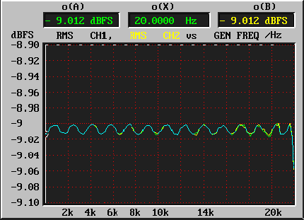
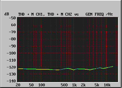
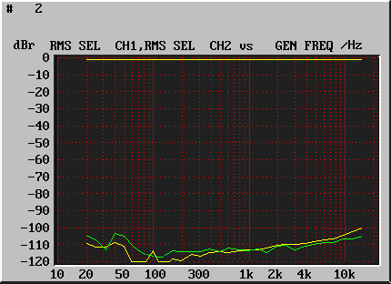
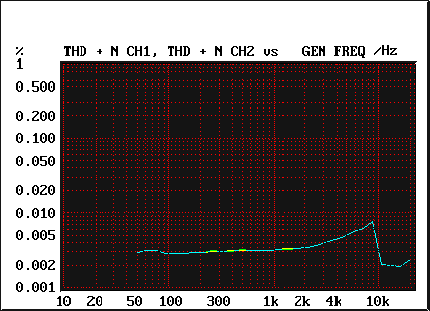
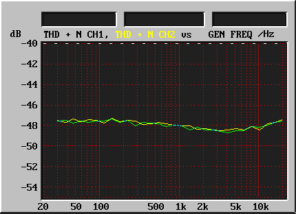
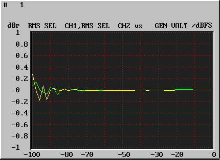
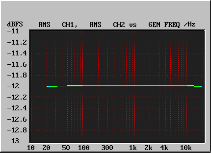
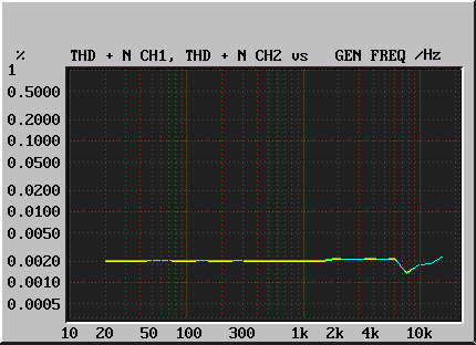
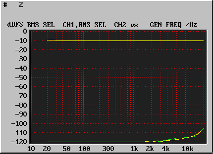
The following diagrams were recorded using an Audio Precision System One analyzer.
The following diagrams were recorded using an Audio Precision System One analyzer.
The following diagrams were recorded using an Audio Precision System One analyzer.

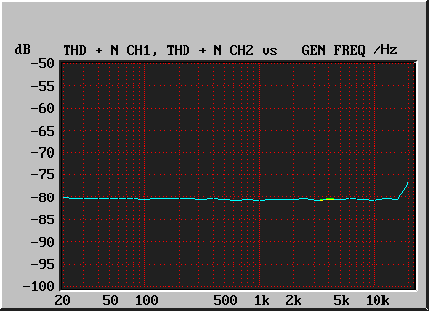
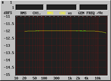
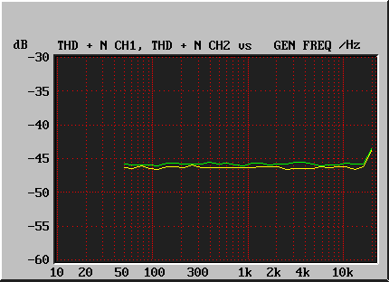

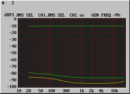

_60dBFS.gif)




_60dBFS.gif)

